4-18
4.1 Electrical Installation
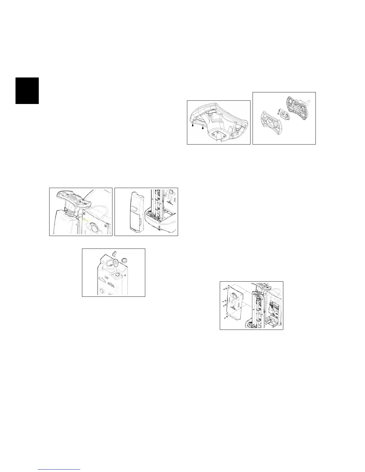
4.1.1 Key Switch
• Put the machine in safe conditions.
• Remove the screws that secure the
front carter to the steering column
(see fig. 4.1.1-1) (see fig. 4.1.1-2).
• Disconnect the wires connected to
the key switch.
• Unscrew the ring nut that secures
the key switch to the steering col-
umn (see fig. 4.1.1-3).
• Remove the key switch.
4.1.1-1 4.1.1-2
4.1.1-3
4.1.2 Control Card
• Put the machine in safe conditions.
• Remove the screws that secure the
upper and lower part of the steering
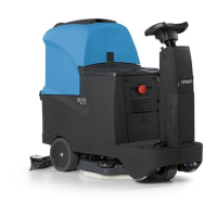
wheel (see fig. 4.1.2-4).
• Separate the top part from the bot-
tom part.
• Disconnect the communication ca-
ble between the Control card and the
Main card.
• Unscrew the screws on the control
card from the top part and remove
the card (see fig. 4.1.2-5).
4.1.2-4 4.1.2-5
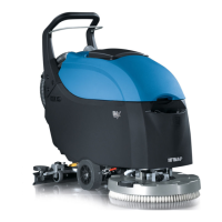
4.1.3 Main Card
• Put the machine in safe conditions.
• Remove the screws to remove the
footrest.
• Remove the screws to remove the
electrical system cover (see fig. 4.5.1-56).
4.1.3-6
• Disconnect the electrical wiring of
the emergency button and of the
Main card.
• Remove the screws that secure the
card to the support bracket.
• Remove the card.