4-20
4.1.6-7 4.1.6-8
4.1.6-9 4.1.6-10
4.2 Mechanical Friction
System
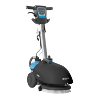
4.2.1 Brush Deck Assembly
• Release the brush from the Brush
Deck.
• Put the machine in safe conditions.
• Make sure that the electrobrake is
enabled.
• Lower the brush deck to the floor.
• Remove the lift arms from the frame.
• Disconnect the electrical connector
of the brush motor and the electric
connector of the solenoid valve.
• Disconnect the solution supply
hose.
• Disconnect the lift chain from the
brush plate.
• Lift the front wheel in order to lift the
front part of the machine of about
20cm.
• Pull off the brush deck sideways to
the machine.
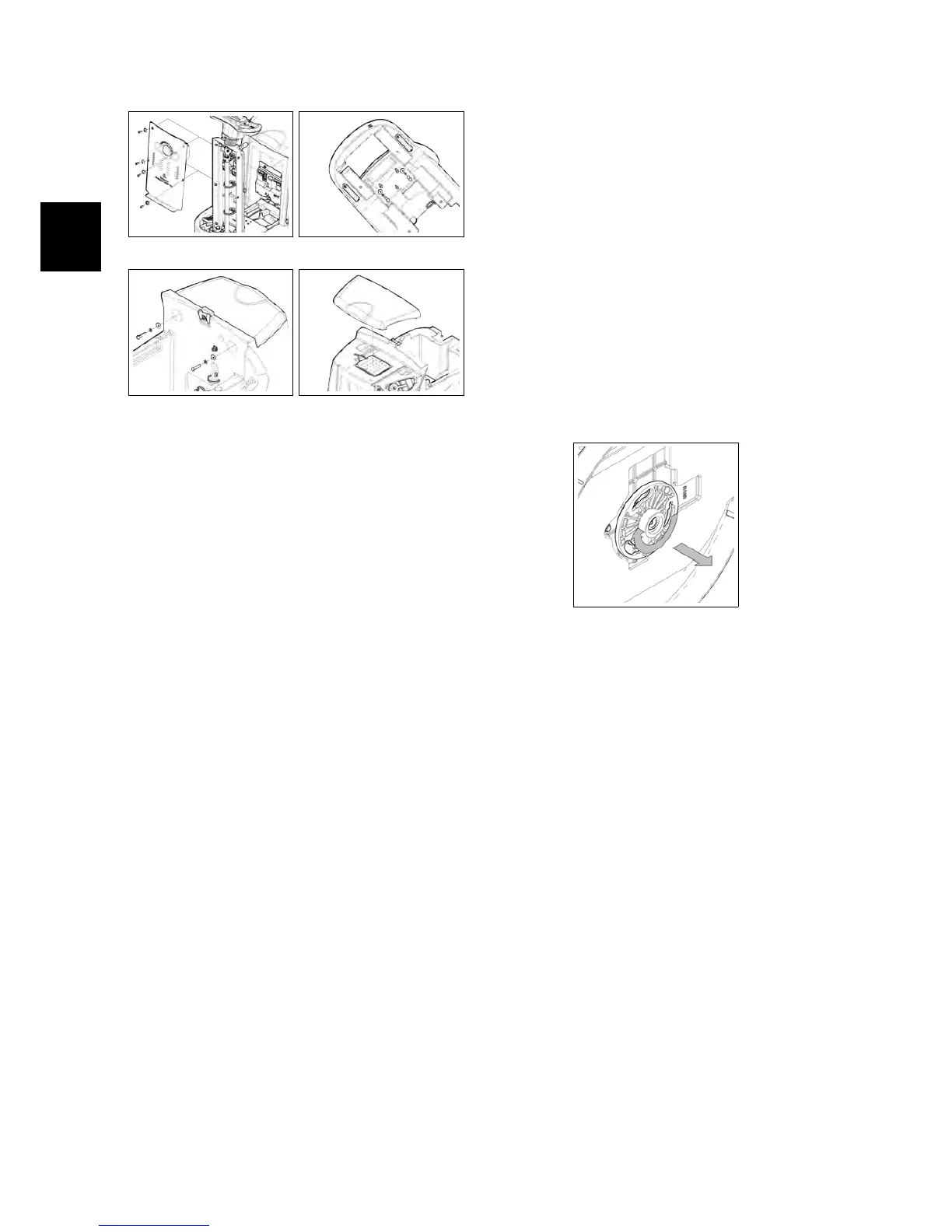
4.2.2 Brush Coupling Flange
• Put the machine in safe conditions.
• Disassemble the Brush Deck from
the machine (see section 4.2.1 at page 20).
• Unscrew the Coupling Flange rotat-
ing it in the same direction as the
brush in standard working condi-
tions.
• Proceed at reverse to refit the part.
Note: Before to refit the part lubricate
the thread in order to prevent blockings
because of dirt or oxide.
4.2.2-11
4.2.3 Brush Motor
• Put the machine in safe conditions.
• Disassemble the Brush Deck from
the machine (see section 4.2.1 at page 20).
• Unscrew the Coupling Flange from
the motor shaft (see section 4.2.2 at page 20).
• Disconnect the electrical connector
of the motor.
• Disconnect the water hose from the
motor (see fig. 4.5.1-58).
• Unscrew the 4 fixing screws and re-
move the motor (see fig. 4.2.3-13).
• Proceed at reverse to refit the part.
Note: Use the thread lock liquid on the
screw during the assembling.