4-27
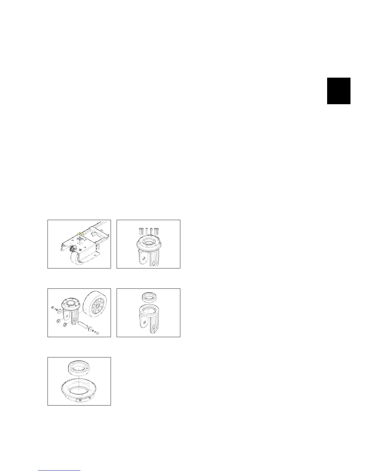
• Remove the sprocket fixing screws
(see fig. 4.4.5-49).
• Remove the sprocket.
• Remove the screws that secure the
cam to the sprocket and remove the
cam.
• Remove the Front Wheel (see fig. 4.4.5-
50).
• Remove the bearings pin.
• Remove the bearings (see fig. 4.4.5-52).
• Proceed at reverse to refit the part.
ATTENTION: WHEN ASSEMBLING, PAY
EXTREME ATTENTION AT THE CORRECT
POSITIONING OF THE SPACER 436224,
BECAUSE IT IS FUNDAMENTAL FOR THE
PROPER FUNCTIONING OF THE PAR T.
4.4.5-48 Fixing screws of
the wheel to the frame
4.4.5-49 Fixing screws of
the steering sprocket
4.4.5-50 Wheel support
pin
4.4.5-51 Bearings in the
wheel fork
4.4.5-52 Bearings on the
steering sprocket
4.5 Solution Delivery Sys-
tem
4.5.1 Solution Tank
• Put the machine in safe conditions.
• Remove the recovery tank (see section
4.3.4 at page 23) (see fig. 4.5.1-53).
• Remove the battery tray (see fig. 4.5.1-54).
• Remove the steering column
carter.(see fig. 4.5.1-55).
• Remove the footrest.
• Remove the electrical installation
carter (see fig. 4.5.1-56).
• Remove the support bracket of the
Main card.
• Remove the traction pedal assembly.
• Remove the seat and the deadman
microswitch (see fig. 4.5.1-57).
• Disconnect the water hose from the
brush deck (see fig. 4.5.1-58).
• Disconnect the control rod from the
water valve (see fig. 4.5.3-62).
• Remove the screws that secure the
solution tank to the machine frame.
• Remove the tank, pulling it out from
the steering column, taking care not
to damage the steering wheel.
• Turn the tank and remove the solu-
tion delivery system (see fig. 4.5.1-60).
• Proceed at reverse to refit the part.
4.5.2 Hoses
• Put the machine in safe conditions.
• Loosen the clamps that hold the
hose to the fitting.