EQUIPMENT: FIRECLASS DUO-CEL
PUBLICATION: OM_DUO-CEL_APP
ISSUE No. & DATE: 2 20/06/18
PAGE 16 of 46
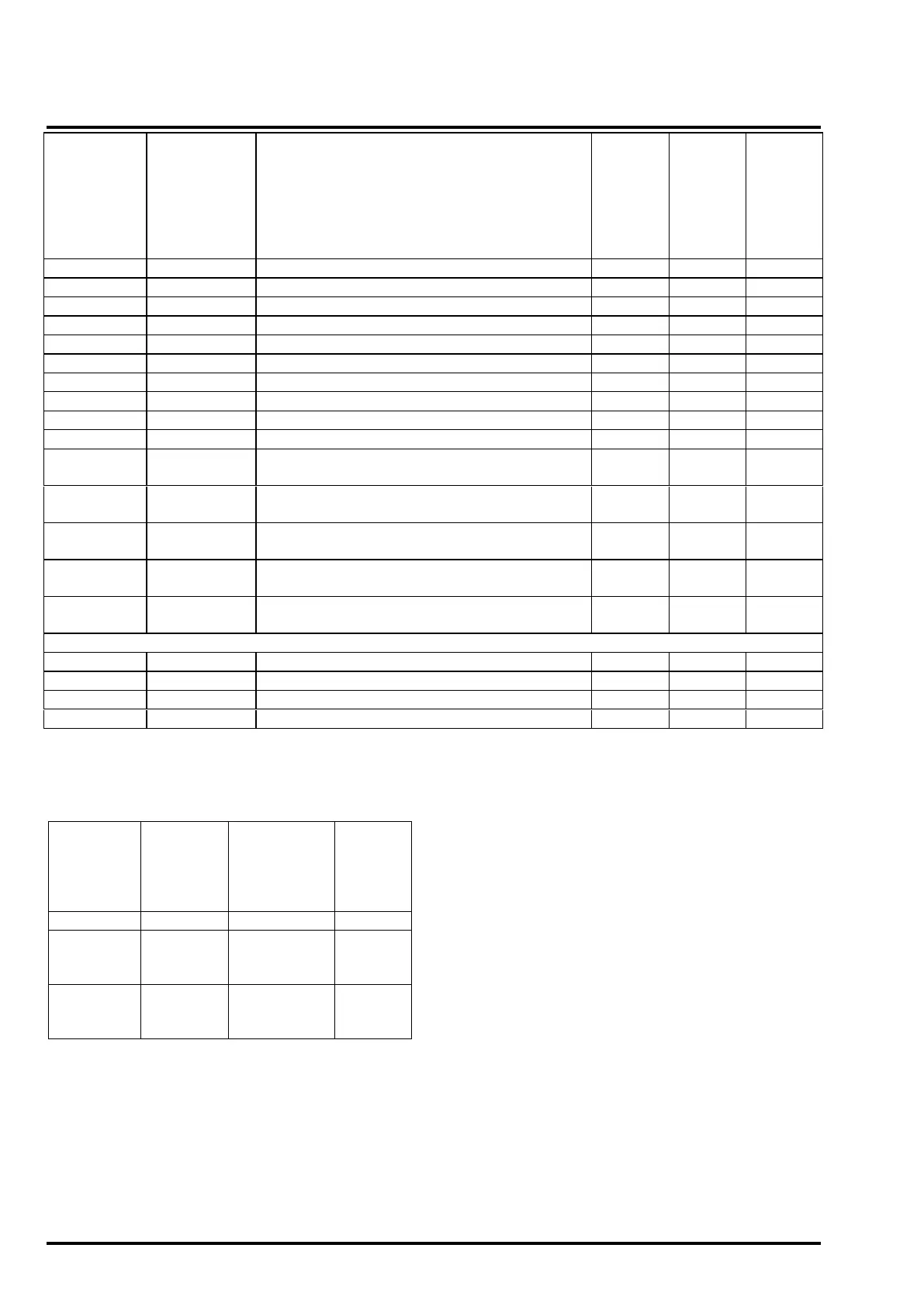
Max.
Devices
Per
standard
zone
(10uF
EOL)
Max.
Devices
Per
Twin-wire
zone
Series 60 integrating ion detector
Series 60 Grade 1 heat detector
Series 60 Grade 2 heat detector
Series 60 Grade 3 heat detector
Series 60 Range 1 heat detector
Series 60 Range 2 heat detector
Series 60 optical detector
Series 60 optical/heat detector
Alert Manual call point (470R)
High Temperature Heat Detector
Base c/w 470R resistor & Diode
2-wire Squashni Sounder Beacon
Notes:
1. The recommended cable is FP200 or MICC
PYRO:
Resistance
per Km
per Core
(Ω)
Capacitance
per Km
Core to Core
(uF)
Capacita
nce per
Km Core
to Screen
(uF)
2. Maximum Cable length is 300m, or 3.63Ω per
core, 63nF core to core & core to screen.
3. The maximum number of detectors and
sounders per zone in section 7.1 assumes no
mixing of devices. The total number of detectors
and/or manual call points per zone must not
exceed 32. This is a recommendation of BS
EN54-2:1997 Annex D. The additional limitations
for twin-wire operation are listed in note (7)
below.
4. The Maximum number of devices per zone is
based on factory default monitoring
configuration [10uF capacitor EOL for the
standard panel or composite device for the twin-
wire panel]. For resistor EOL or Twin-Wire, the
total quiescent current drawn per zone by all
devices on the zone should not exceed 1.6mA.
Exceeding this current will result in a failure to
correctly detect an open circuit or head removal.
5. The number in brackets for the twin-wire zone is
the maximum number of devices allowed if NO
twin-wire sounders are connected to the zone.
6. The values are for guidance only and will vary
for individual detectors and cable types. Each
zone must be fully checked for correct operation
& fault monitoring during installation &
commissioning.
7. When using twin-wire sounders, observe the
following additional requirements:
a. DO NOT exceed the maximum number of
sounders per zone as listed in the above
table in section 7.1. These figures are based
on extensive testing and allow for operation