Instruction Manual
D102748X012
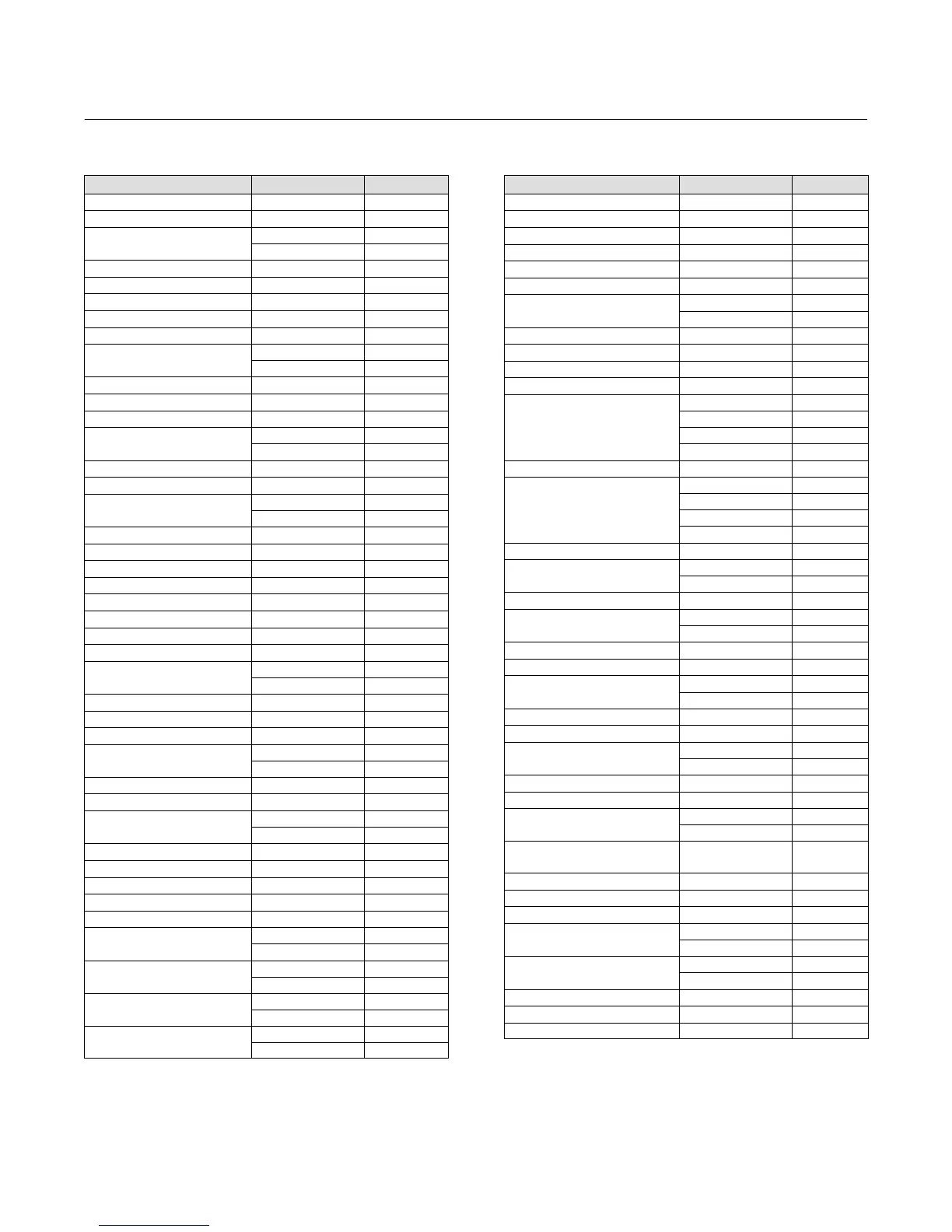
Field Communicator Menu Tree
October 2014
100
Table
B‐1.
Fast
Key
Sequence
Function Fast-Key Sequence See Figure
Active Alerts 3-1 B‐8
Alarm Jumper 1-7-3-1-1 B‐2
Analog Output
1-5 B‐2
3-2-3 B‐8
Burst Mode 2-4-1 B‐6
Burst Options 2-4-2 B‐6
Calibration, Full 2-5-1-2 B‐7
Calibration, Partial 2-5-1-3 B‐7
Calibration, Temperature 2-5-2-1 B‐7
Change Process Temperature
2-2-3-2
(1)
B‐4
2-2-3-2-2
(2)
B‐4
Change Primary Variable 2-2-2-1-2 B‐1
Change Torque Rate 2-2-1-3-2 B‐4
Comm Status 1-2 B‐2
Date
1-7-1-8 B‐2
2-2-4-2 B‐4
DD Information 1-7-2-5 B‐2
Decimal Places 2-2-5-4 B‐4
Descriptor
1-7-1-9 B‐2
2-2-4-3 B‐4
Device ID 1-7-1-4 B‐2
Device Status 1-1 B‐2
Displacer Units 2-2-1-2 B‐4
Display Alert/Saturation Level 1-7-3-1-2 B‐2
Display Mode 2-2-5-2 B‐4
Distributor 1-7-1-2 B‐2
Enter Constant Density 2-2-3-1-3
(2)
B‐1
Field Device Revision 1-7-2-2 B‐2
Final Assembly Number
1-7-1-7 B‐2
2-2-4-8-3 B‐4
Firmware Revision 1-7-2-3 B‐2
Guided Setup 2-1 B‐3
Hardware Revision 1-7-2-4 B‐2
HART Tag
1-7-1-1 B‐2
2-2-4-1 B‐4
HART Universal Revision 1-7-2-1 B‐2
Instrument Mounting 2-2-1-4 B‐4
Instrument Serial Number
1-7-1-5 B‐2
2-2-4-8-1 B‐4
Instrument Temperature 3-2-4 B‐8
Instrument Temperature Alerts 2-3-2-1 B‐5
LCD Configuration 2-2-5-1 B‐4
LCD Test 3-3-1-1
(3)
B‐8
Level Offset 2-2-2-1-4 B‐4
Loop Test
3-3-1-1 B‐8
3-3-1-2
(3)
B‐8
Lower Density Table
2-2-3-1-1-1
(4)
B‐4
2-2-3-1-1-2
(5)
B‐4
Lower Fluid Density
2-2-3-1-1 or 3-2-7
(4)
B‐4
2-2-3-1-2 or 3-2-8
(5)
B‐4
Lower Range Value
2-2-2-3-2 B‐4
2-3-1-4 B‐5
Function Fast-Key Sequence See Figure
Lower Sensor Limit 2-2-2-2-2 B‐4
Measure Density 2-2-3-1-4
(4)
B‐4
Message 2-2-4-4 B‐4
Minimum Sensor Span 2-2-2-2-3 B‐4
Model 1-7-1-3 B‐2
Number of Request Preambles 2-2-4-7 B‐4
Percent Range
1-4-2 B‐2
3-2-2-2 B‐8
Physical Signalling Code 2-2-4-6 B‐4
Polling Address 2-2-4-5 B‐4
Primary Variable Hi Alerts 2-3-1-1 B‐5
Primary Variable Lo Alerts 2-3-1-2 B‐5
Process Temperature
1-6-2 B‐2
2-2-3-2-3
(2)
B‐4
2-2-3-3
(1)
B‐4
3-2-5-2 B‐8
Process Temperature Alerts 2-3-2-2 B‐5
Process Temperature Source
1-6-1 B‐4
2-2-3-2-1
(2)
B‐4
2-2-3-
(1)
B‐2
3-2-5-1 B‐8
PV Alerts Threshold Deadband 2-3-1-5 B‐5
PV is
1-3 B‐2
2-2-2-1-1 B‐4
PV Units 2-2-2-1-3 B‐4
PV Value
1-4-1 B‐2
3-2-2-1 B‐8
Reset Device 3-3-2-2 B‐8
Restore Factory Defaults 3-3-2-1 B‐8
RTD Wire Resistance
2-2-3-2-4
(2)
B‐4
2-2-3-4
(1)
B‐4
Scaled D/A Trim 2-5-2-2-1 B‐7
Sensor Damping 2-2-1-5 B‐4
Sensor Serial Number
1-7-1-6 B‐2
2-2-4-8-2 B‐4
Sensor Unit 2-2-1-1 B‐4
Set Level Offset 2-2-2-1-5 B‐4
Torque Rate
2-2-1-3-1 B‐4
3-2-6 B‐8
Torque Tube Compensation
Selection
2-2-1-3-4 B‐4
Torque Tube Compensation Table 2-2-1-3-5 B‐4
Torque Tube Material 2-2-1-3-3 B‐4
Upper Density Table 2-2-3-1-1-1
(4)
B‐4
Upper Fluid Density
2-2-3-1-1
(4)
B‐4
3-2-7
(4)
B‐8
Upper Range Value
2-2-2-3-1 B‐4
2-3-1-3 B‐5
Upper Sensor Limit 2-2-2-2-1 B‐4
Write Lock 1-7-3-2-1 B‐1
Write Lock Setup 1-7-3-2-2 B‐1
1. If PV is Density
2. If PV is Level or Interface.
3. LCD Configuration is installed
4. If PV is Level
5. If PV is Interface
 Loading...


