Instruction Manual
D102748X012
Field Communicator Menu Tree
October 2014
102
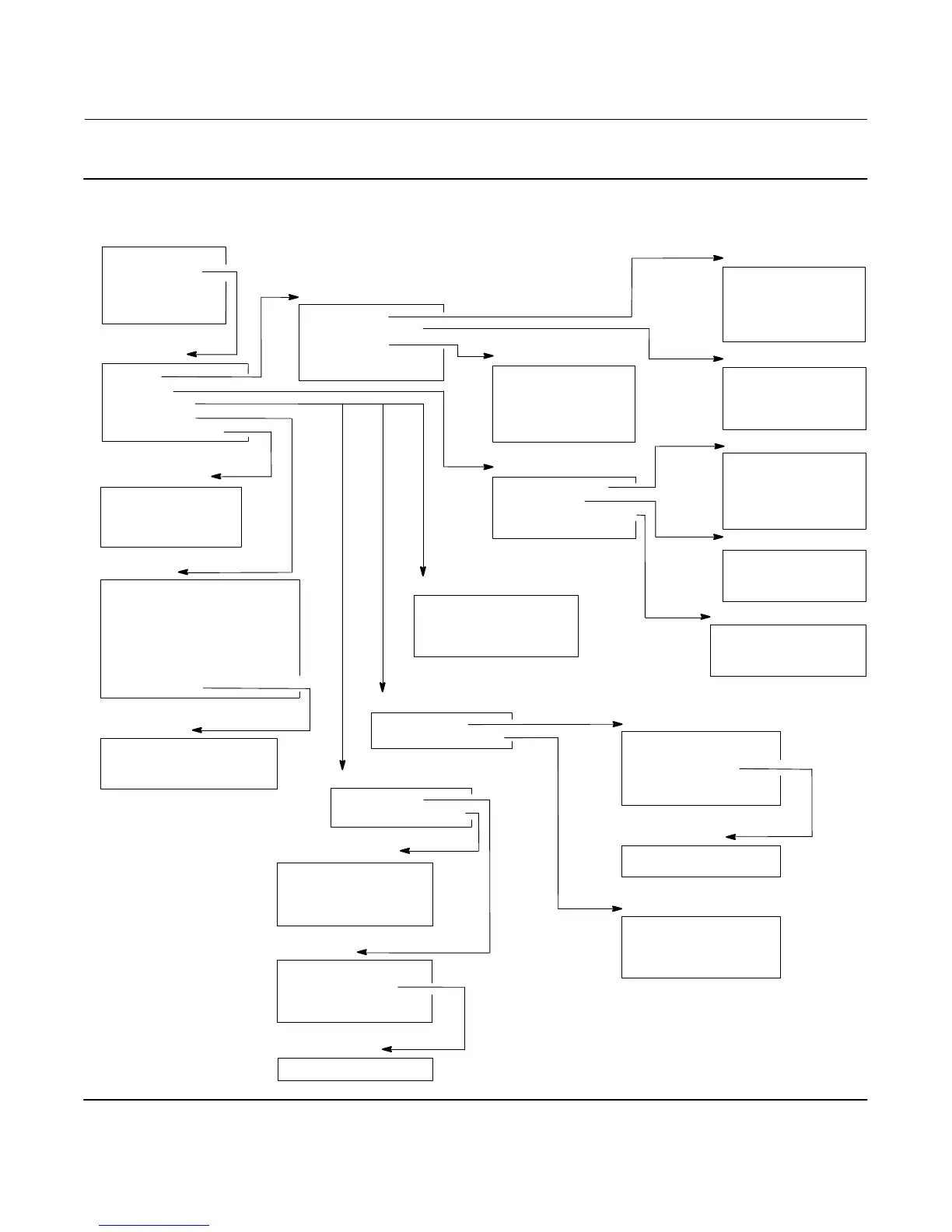
Figure B‐4. Configure > Manual Setup
Sensor Units
1 Length Units
2 Volume Units
3 Weight Units
4 Torque Rate Units
5 Temperature Units
Manual Setup
1 Sensor
2 Variables
3 Process Fluid
4 Identification
5 Instrument Display
2‐2‐1
Variables
1 Primary Variables
2 Sensor Limits
3 Primary Variable Range
4 PV Damping
Identification
1 HART Tag
2 Date
3 Descriptor
4 Message
5 Polling Address
6 Physical Signaling Code
7 Number of Request Preambles
8 Serial Numbers
Sensor
1 Sensor Units
2 Sensor Dimensions
3 Torque Tube
4 Instrument Mounting
5 Sensor Damping
Sensor Dimensions
1 Displacer Length
2 Displacer Volume
3 Displacer Weight
4 Driver Rod Length
Torque Tube
1 Torque Rate
2 Change Torque Rate
3 TT Material
4 TT Comp Selection
5 TT Comp Table
2‐2‐1-1
2‐2‐1-2
2‐2‐1-3
Primary Variables
1 PV is
2 Change PV
3 PV Units
4 Level Offset
5 Set Level Offset
Instrument Display
1 LCD Configuration
2 Display Mode
3 Change Display Mode
4 Decimal Places
2‐2‐5
Sensor Limits
1 Upper Sensor Limit
2 Lower Sensor Limit
3 Minimum Span
Primary Variable Range
1 Upper Range Value
2 Lower Range Value
3 View/Change AO Action
2‐2‐2
2‐2‐2-1
2‐2‐2-2
2‐2‐2-3
Process Fluid (if PV is Level)
1 Process Fluid
2 Process Temperature
Process Fluid
1 Lower Fluid Density
2 View Fluid Tables
3 Enter Constant Density
4 Measure Density
Process Temperature
1 Proc Temp Source
2 Change Proc Temp
3 Proc Temp
4 RTD Wire Resistance
Serial Numbers
1 Instrument Serial Number
2 Sensor Serial Number
3 Final Assembly Number
2‐2‐4
2‐2‐4-8
2‐2‐3
2‐2‐3
Process Fluid (if PV is Interface)
1 Process Fluids
2 Process Temperature
Process Fluids
1 Upper Fluid Density
2 Lower Fluid Density
3 View Fluid Tables
4 Enter Constant Density
5 Load Steam Tables
2‐2‐3
Process Fluid (if PV is Density)
1 Proc Temp Source
2 Change Proc Temp
3 Proc Temp
4 RTD Wire Resistance
If PV is Density
If PV is Interface
If PV is Level
Process Temperature
1 Proc Temp Source
2 Change Proc Temp
3 Proc Temp
4 RTD Wire Resistance
2‐2‐3-1
2‐2‐3-2
View Fluid Tables
1 Lower Density Table
2‐2‐3-1-2
View Fluid Tables
1 Upper Density Table
2 Lower Density Table
2‐2‐3-1-3
2‐2‐3-1
2‐2‐3-2
Configure
1 Guided Setup
2 Manual Setup
3 Alert Setup
4 Communications
5 Calibration
2‐2
2
 Loading...


