Instruction Manual
D103176X012
Viewing Device Variables and Diagnostics
June 2017
36
D Failure Alerts—If a self-test failure has occurred, it will appear when the Failure Alerts menu item is selected. If there
are multiple failures, they will appear on the display one at a time in the order listed below.
1. Offline/Failed—This failure indicates a failure, enabled from the Self Test Shutdown menu, caused an instrument
shutdown. Press Enter to see which of the specific failures caused the Offline/Failed indication.
2. Travel Sensor Fail—This failure indicates the sensed travel is outside the range of -25.0 to 125.0% of calibrated
travel. If this failure is indicated, check the instrument mounting.
3. Pressure Sensor Fail—This failure indicates the actuator pressure is outside the range of -24.0 to 125.0% of the
calibrated pressure for more than 60 seconds. If this failure is indicated, check the instrument supply pressure. If
the failure persists, ensure the printed wiring board assembly is properly mounted onto the mounting frame, and
the pressure sensor O-rings are properly installed. If the failure does not clear after restarting the instrument,
replace the printed wiring board assembly.
4. Temperature Sensor Fail—This failure is indicated when the instrument temperature sensor fails, or the sensor
reading is outside of the range of -40 to 85°C (-40 to 185°F). The temperature reading is used internally for
temperature compensation of inputs. If this failure is indicated, restart the instrument and see if it clears. If it
does not clear, replace the printed wiring board assembly.
5. NVM Fail—This failure is indicated when the Non-Volatile Memory integrity test fails. Configuration data is stored
in NVM. If this failure is indicated, restart the instrument and see if it clears. If it does not clear, replace the
printed wiring board Assembly.
6. Drive Current Fail—This failure is indicated when the drive current does not read as expected. If this failure occurs,
check the connection between the I/P converter and the printed wiring board assembly. Try removing the I/P
converter and re-installing it. If the failure does not clear, replace the I/P converter or the printed wiring board
assembly.
7. Ref Voltage Fail—This failure is indicated whenever there is a failure associated with the internal voltage reference.
If this failure is indicated, restart the instrument and see if it clears. If it does not clear, replace the printed wiring
board assembly.
8. Flash ROM Fail—This failure indicates the Read Only Memory integrity test failed. If this failure is indicated, restart
the instrument and see if it clears. If it does not clear, replace the printed wiring board assembly.
D Alert Record—The instrument contains an alert record that can store up to 20 alerts from any of the enabled alert
groups: Valve Alerts or Failure Alerts. See the Advanced Setup section for information on enabling alert groups.
Table 3‐2 lists the alerts included in each of the groups. The alert record also includes the date and time (from the
instrument clock) the alerts occurred.
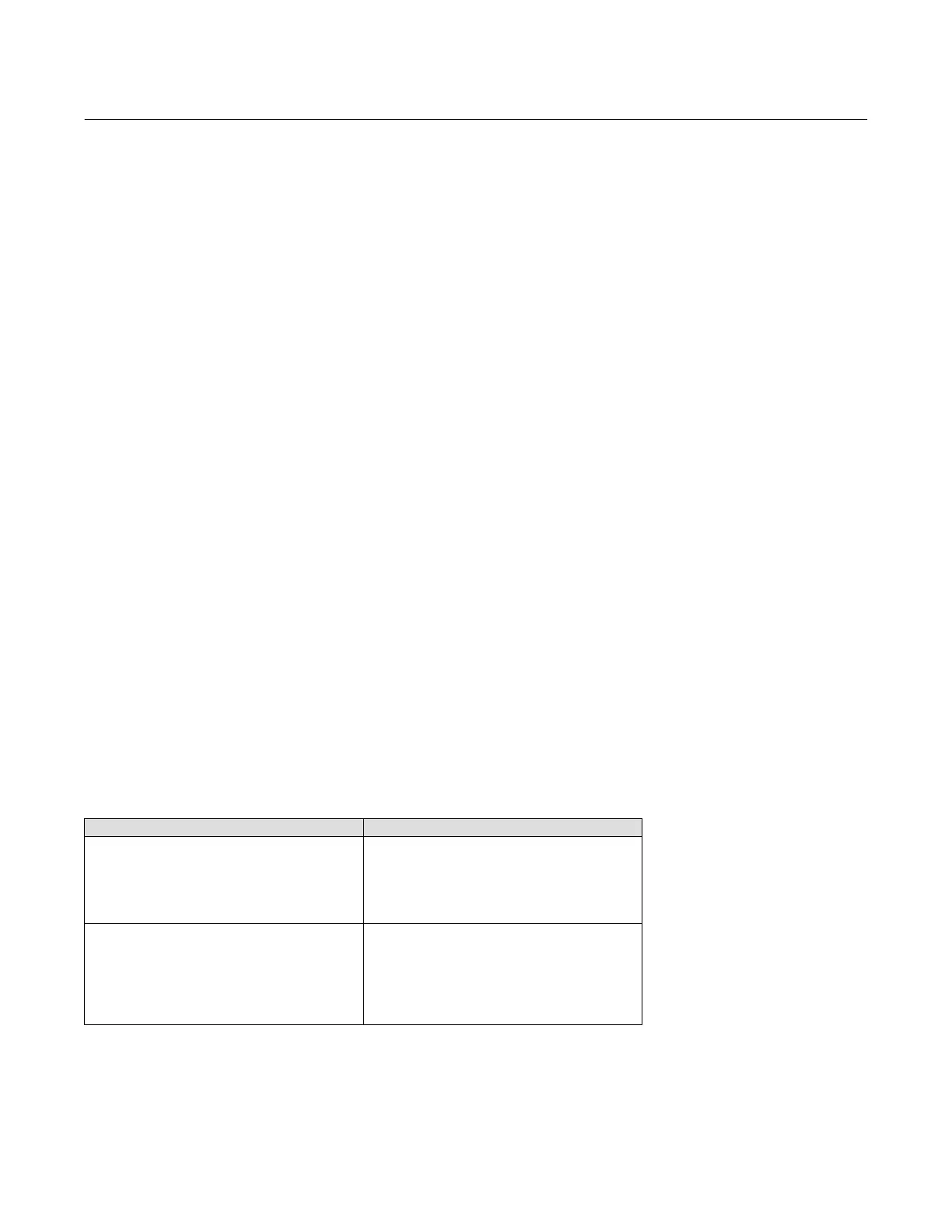
Table 3‐2. Alerts Included in Alert Groups for Alert Record
Alert Group Alerts Included in Group
Valve Alerts
Travel Alert Lo
Travel Alert Hi
Travel Alert Lo Lo
Travel Alert Hi Hi
Travel deviation
Drive signal
Failure Alerts
Flash ROM Shutdown
Drive Current Shutdown
Reference Voltage Shutdown
Critical NVM Shutdown
Temperature Sensor Shutdown
Pressure Sensor Shutdown
Travel Sensor Shutdown
 Loading...


