Maintenance and Troubleshooting
June 2017
Instruction Manual
D103176X012
42
Note
After I/P converter replacement, calibrate the digital valve controller to maintain accuracy specifications.
Removal
1. Remove the main cover.
2. Remove three screws that hold the EMI shield and remove the shield (refer to figure 4‐1).
3. Remove the three screws holding the electronics board to the mounting frame.
4. Pull the main electronics straight off of the mounting frame. The board is electrically connected to an
interconnecting board with a rigid connector.
5. Remove the two screws holding the mounting frame to the instrument housing (refer to figure 4‐2 for location of
screws).
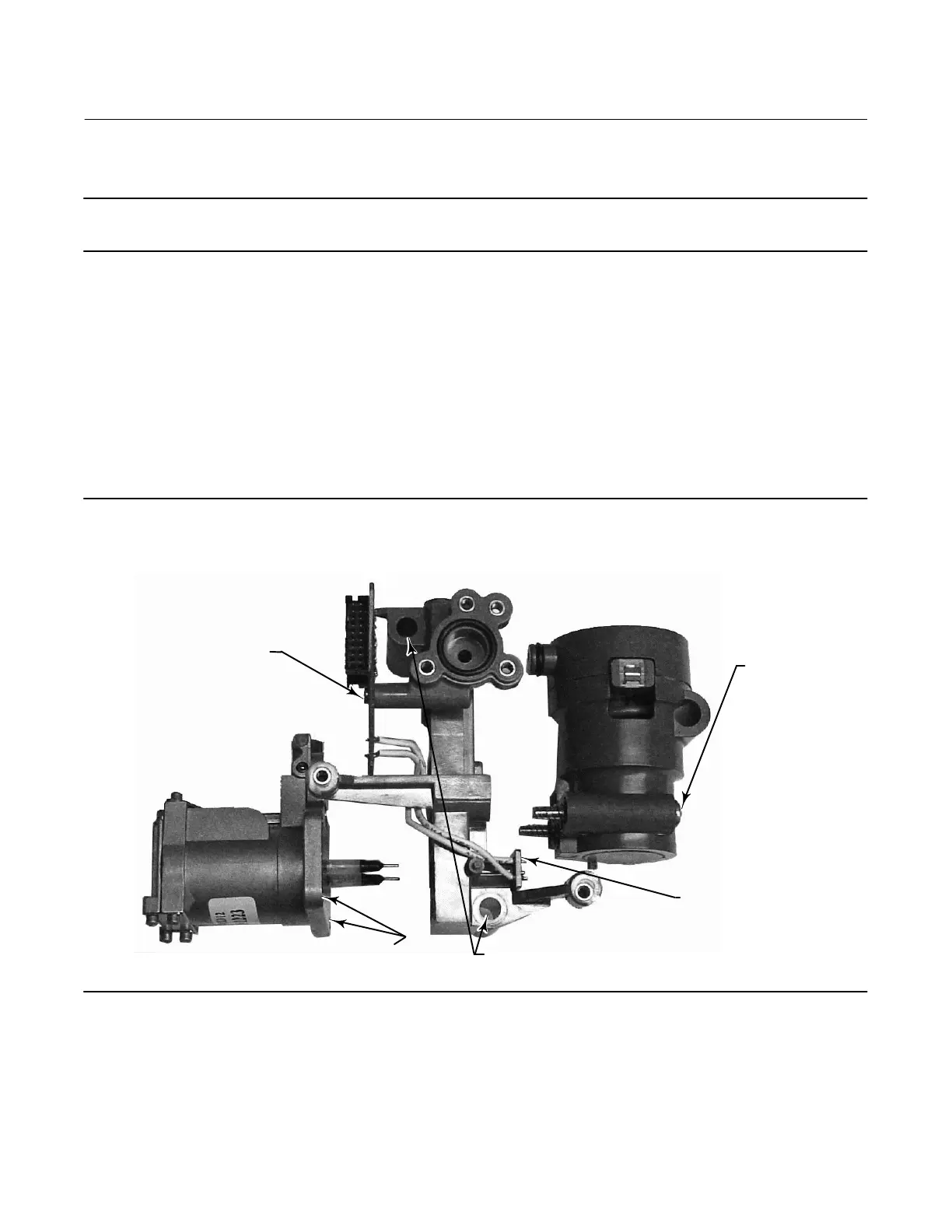
Figure 4‐2. Mounting Frame Assembly
INTERCONNECT
BOARD SCREW (1)
I/P CONVERTER SCREW HOLES (4)
(SCREWS NOT SHOWN)
MOUNTING FRAME SCREW HOLES (2)
(SCREWS NOT SHOWN)
I/P BOARD SCREW (1)
PNEUMATIC
RELAY SCREWS (2)
MANIFOLD
ASSEMBLY
INTERCONNECT
BOARD
W9103
6. Pull the manifold assembly straight out. The interconnecting board is electrically connected to the termination
board with a rigid connector.
7. Remove the interconnect board from the mounting frame.
8. Remove the four screws holding the I/P converter to the mounting frame (refer to figure 4‐2 for location of screws).
9. Pull the I/P converter straight out taking care to capture the two o-rings (one has a screen).
 Loading...


