Instruction Manual
D103412X012
Detailed Setup—AO Function Block
July 2013
114
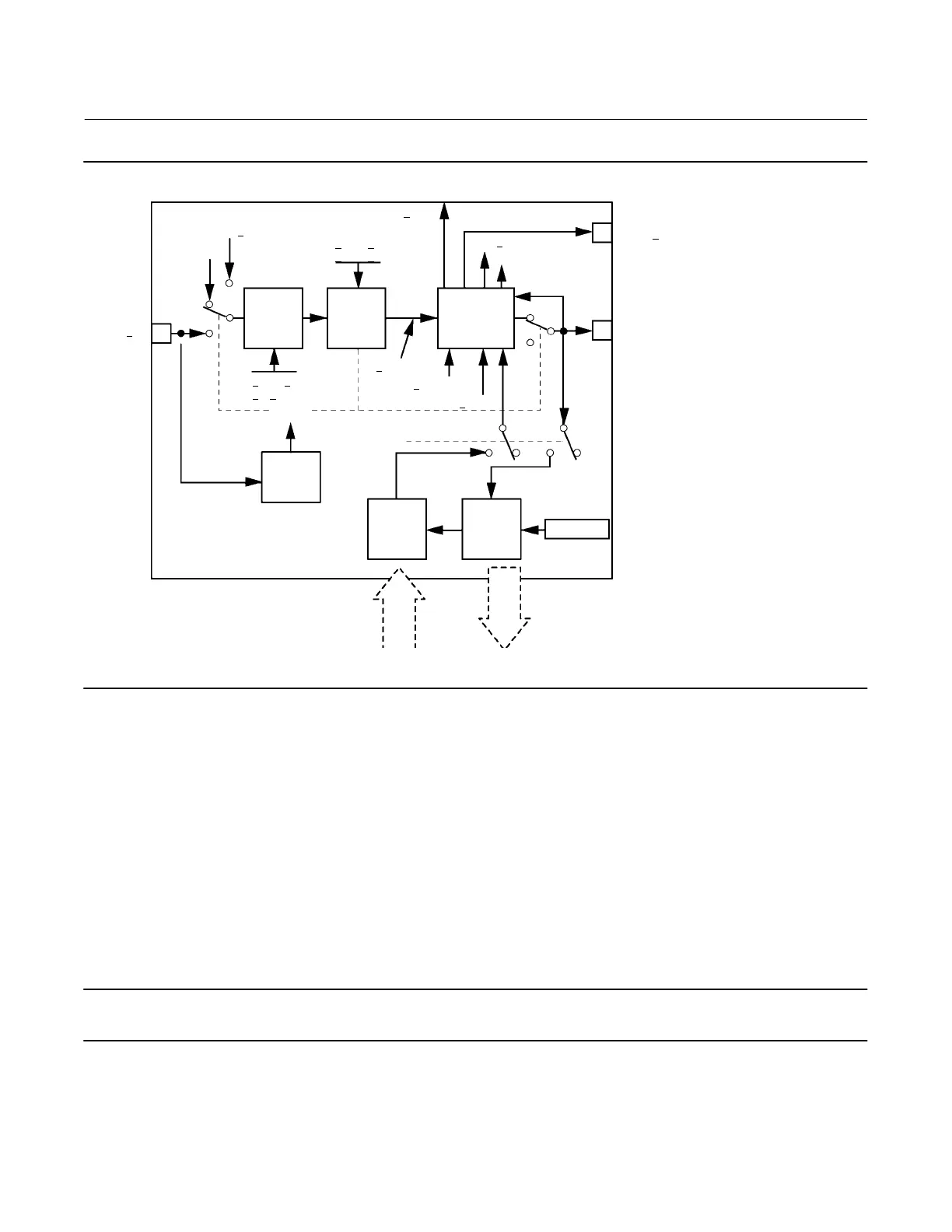
Figure 4‐7. Analog Output Function Block Schematic
B2717
CAS IN
Position
Feedback
Analog
Output
Access
Analog
Output
Access
Analog
Input
Shed
Mode
SP
HI/LO
Limit
SP
Rate
Limit
Convert
and Status
Calculation
BKCAL
OUT
OUT
RCAS
OUT
RCAS
IN
SP
RATE DN
SP
RATE UP
SP
WRK
PV
SCALE
IO
OPTS
Operator
Setpoint
READ
BACK
PV
SP
LOW LIM
SP
HI LIM
CHANNEL
MODE
Modes
The Analog Output function block supports the following modes:
Manual (Man)—You can manually set the output to the I/O channel through the OUT [9] attribute. This mode is used
primarily for maintenance, calibration and diagnostics.
Automatic (Auto)—The block output (OUT [9]) reflects the target operating point specified by the setpoint (SP [8])
attribute. Typically the setpoint is set by the user.
Cascade (Cas)—The SP [8] attribute is set by another function block through a connection to CAS_IN [17]. The SP [8]
value is used to set the OUT [9] attribute automatically. This is the most frequently used mode in the digital valve
controller.
Note
The transducer block must be in Auto for the mode to go to AUTO, CAS, MAN, or RCAS.
RemoteCascade (RCas)—The SP [8] is set by a host computer by writing to the RCAS_IN [28] parameter. The SP [8]
value is used to set the OUT [9] attribute automatically.
 Loading...


