Instruction Manual
D103412X012
FOUNDATION fieldbus Communication
July 2013
288
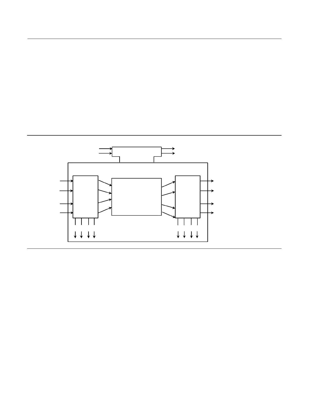
Figure D‐1 illustrates the internal structure of a function block. When execution begins, input parameter values from
other blocks are snapped‐in by the block. The input snap process ensures that these values do not change during the
block execution. New values received for these parameters do not affect the snapped values and will not be used by
the function block during the current execution.
Function blocks are also capable of performing short‐term data collection and storage for reviewing their behavior.
Instrument‐Specific Blocks
In addition to function blocks, fieldbus devices contain two other block types to support the function blocks. These are
the resource block and the transducer block. The resource block contains the hardware specific characteristics
associated with a device. Transducer blocks couple the function blocks to local input/output functions.
Figure D‐1. Function Block Internal Structure
Input
Events
Output
Events
Processing
Algorithm
Output
Snap
Input
Snap
Input Parameter
Linkages
status status
Execution Control
Output
Parameter
Linkages
B2711
Resource Blocks
The resource block contains hardware specific characteristics associated with the device; it has no input or output
parameters. The algorithm within a resource block monitors and controls the general operation of the physical device
hardware. The execution of this algorithm is dependent on the characteristics of the physical device, as defined by the
manufacturer. As a result of this activity, the algorithm may cause the generation of events. There is only one resource
block defined for a device. For example, placing the resource block in Out of Service mode stops all function block
execution, by setting their modes to Out of Service as well. The actual mode of the function blocks is changed to Out
of Service, but the function block target modes will not change. Placing the resource block in the Out of Service mode
does not affect the mode of the transducer block.
Transducer Blocks
Transducer blocks connect function blocks to local input/output functions. They read sensor hardware and write to
effector (actuator) hardware. This permits the transducer block to execute as frequently as necessary to obtain good
data from sensors and ensure proper writes to the actuator without burdening the function blocks that use the data.
The transducer block also isolates the function block from the specific characteristics of the physical I/O.

 Loading...


