Instruction Manual
D103412X012
Maintenance and Troubleshooting
July 2013
236
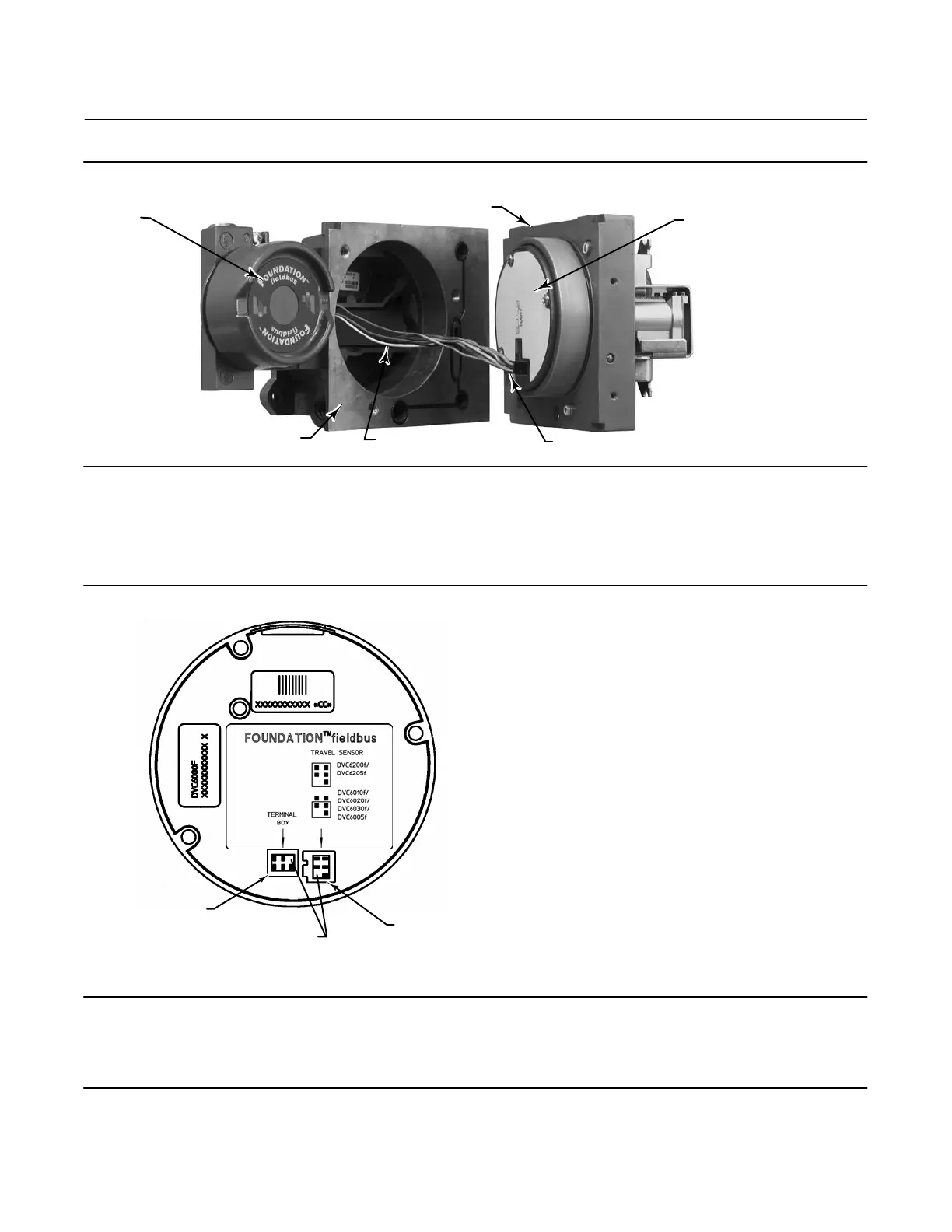
Figure 7‐1. Printed Wiring Board Cable Connections
HOUSING
W9924‐1
CABLE TO TRAVEL SENSOR
PRINTED WIRING
BOARD
ASSEMBLY
CABLE
TO TERMINAL BOX
TERMINAL
BOX
MODULE BASE ASSEMBLY
Replacing the Module Base
Refer to figure 8‐2 or 8‐4 for key number locations. Refer to figure 7‐2 for a view of the back of the PWB assembly
sub‐module.
Figure 7‐2. Back View of PWB Assembly Sub‐Module
GE39341
PINS REMOVED FOR
CONNECTOR KEYING
TERMINAL BOX
CONNECTOR
TRAVEL SENSOR CONNECTOR
S
S
Note
To avoid affecting performance of the instrument, inspect the guide surface on the module and the corresponding seating area in
the housing before installing the module base assembly. These surfaces must be free of dust, dirt, scratches, and contamination.
Ensure the module base seal is in good condition. Do not reuse a damaged or worn seal.
 Loading...


