Instruction Manual
D103412X012
Installation
July 2013
20
8. Check for clearance between the magnet assembly and the DVC6215 feedback slot.
Note
Ensure that there is clearance between the magnet assembly and the DVC6215 housing slot throughout the full range of travel.
Fisher Rotary Actuators and Sliding‐Stem Linear Actuators over 210 mm (8.25 Inches) Travel
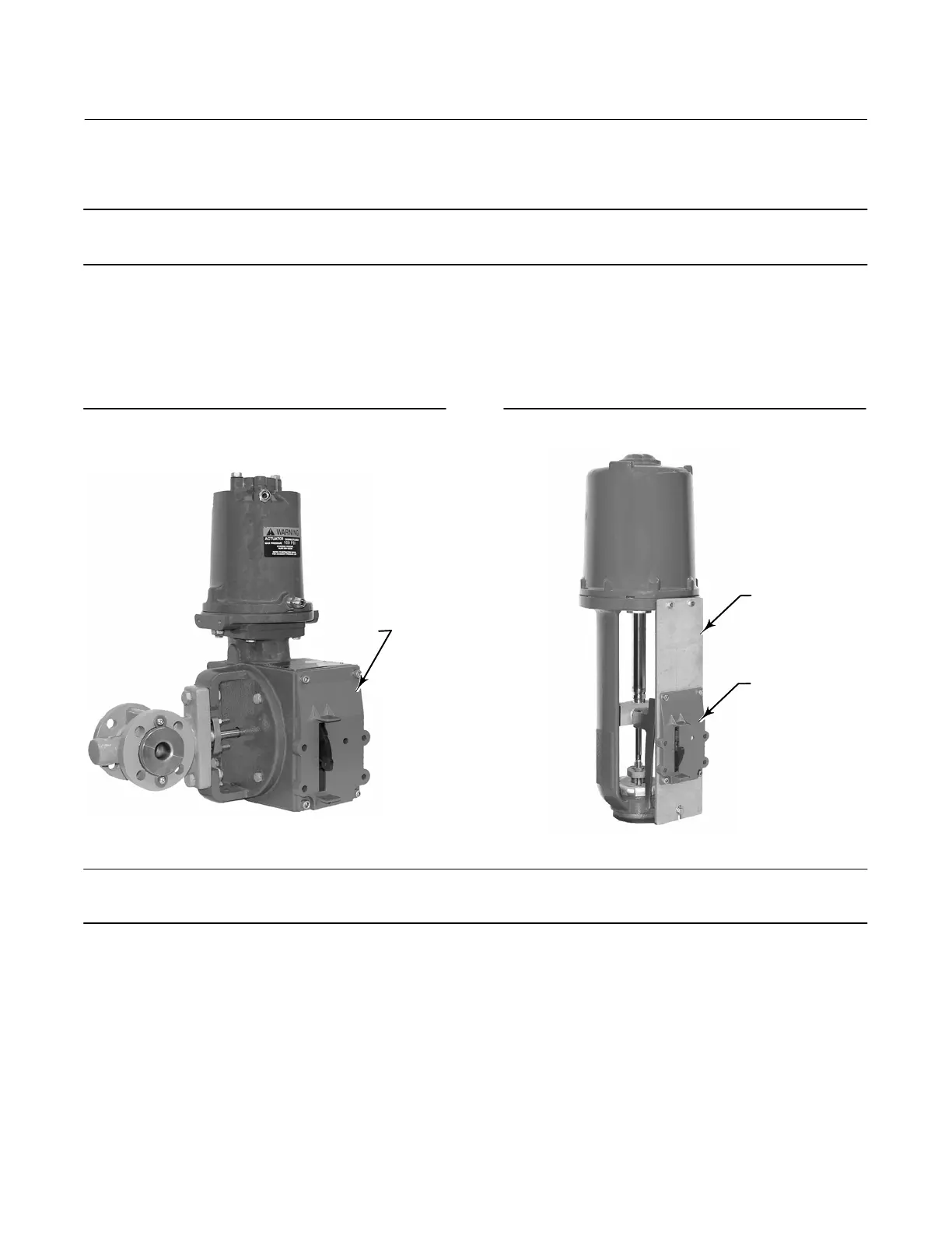
The DVC6215 feedback unit uses a cam (designed for linear response) and roller as the feedback mechanism. See
figures 2‐12 and 2‐13.
Figure 2‐12. Mounting on Rotary Actuators
ROTARY MOUNTING
KIT (DVC6215 NOT
SHOWN)
W9708
Figure 2‐13. Mounting on Sliding‐Stem (Linear)
Actuators over 210 mm (8.25 Inches) Travel
LONG STROKE
MOUNTING
KIT (DVC6215
NOT SHOWN)
MOUNTING
ADAPTOR
W9709
Note
All cams supplied with FIELDVUE mounting kits are characterized to provide a linear response.
There are three different mounting adaptions, based on the actuator design (see figure 2‐14).
Fisher Rotary Actuators
Refer to the following guidelines when mounting on rotary actuators.
1. Isolate the control valve from the process line pressure and release pressure from both sides of the valve body. Shut
off all pressure lines to the pneumatic actuator, releasing all pressure from the actuator. Use lock‐out procedures to
be sure that the above measures stay in effect while working on the equipment.

 Loading...


