Instruction Manual
D103412X012
Installation
July 2013
19
3. Loosely attach the feedback pieces and magnet assembly to the valve stem connector. Do not tighten the fasteners
because fine adjustment is required.
CAUTION
Do not install a magnet assembly that is shorter than the physical travel of the actuator. Loss of control will result from the
magnet assembly moving outside the range of the index mark in the feedback slot of the DVC6215 housing.
4. Using the alignment template (supplied with the mounting kit), position the magnet assembly inside the retaining
slot.
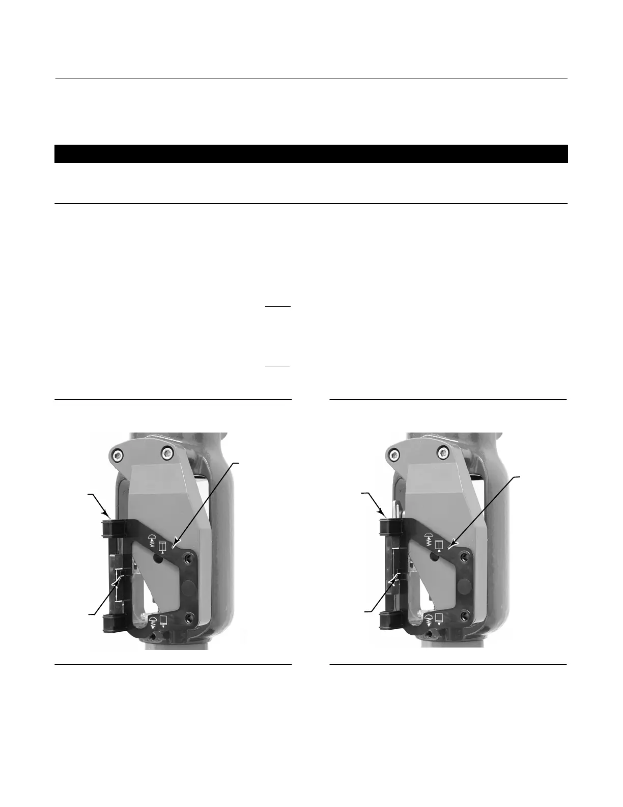
5. Align the magnet assembly as follows:
For air‐to‐open actuators (e.g. Fisher 667) vertically align the magnet assembly so that the center line of the alignment
template is lined up as close as possible with the upper
extreme of the valid travel range on the magnet assembly. The
magnet assembly should be positioned so that the index mark in the feedback slot of the DVC6215 housing is within
the valid range on the magnet assembly throughout the range of travel. See figure 2‐10.
For air‐to‐close actuators (e.g. Fisher 657) vertically align the magnet assembly so that the center line of the alignment
template is lined up as close as possible with the lower
extreme of the valid travel range on the magnet assembly. The
magnet assembly should be positioned so that the index mark in the feedback slot of the DVC6215 housing is within
the valid range on the magnet assembly throughout the range of travel. See figure 2‐11.
Figure 2‐10. Air‐to‐Open Magnet Assembly
Alignment
W9718
ALIGNMENT
TEMPLATE
INDEX
MARK
RETAINING
SLOT
Figure 2‐11. Air‐to‐Close Magnet Assembly
Alignment
ALIGNMENT
TEMPLATE
W9719
RETAINING
SLOT
INDEX
MARK
6. Tighten the fasteners and remove the alignment template.
7. Mount the feedback unit to the mounting bracket, using the mounting bolts.
 Loading...


