Instruction Manual
D103412X012
Detailed Setup—DI Function Block
July 2013
201
Discrete Input Function Block
Overview
The Discrete Input (DI) function block (figure 4‐29) processes a single discrete input from a field device and makes it
available to other function blocks. You can configure inversion and alarm detection on the input value. In the
DVC6200f digital valve controller, the discrete input function block can provide limit switch functionality and valve
position proximity detection. The DI function block supports mode control, signal status propagation, and simulation.
Figure 4‐29. Discrete Input (DI) Function Block
DI
OUT_D = The block output and status
OUT_D
TRANSDUCER
BLOCK
Normally, the block is used in Automatic mode so that the process variable (PV_D [7]) is copied to the output (OUT_D
[8]). You can change the mode to Manual to disconnect the field signal and substitute a manually‐entered value for
the output. In this case, PV_D [7] continues to show the value that will become the OUT_D [8] when the mode is
changed to Automatic.
To support testing, you can enable simulation, which allows the measurement value to be supplied manually through
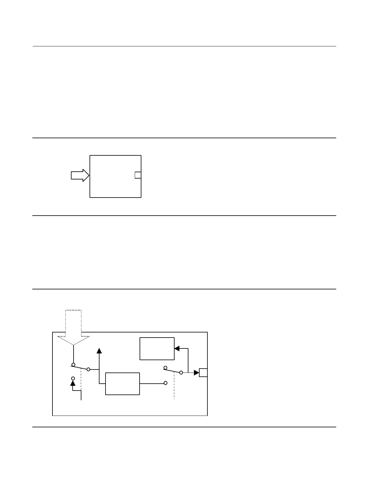
the SIMULATE_D [9] parameter. Figure 4‐30 illustrates the internal components of the DI function block, and table
4‐81 lists the definitions of the block parameters.
Figure 4‐30. Discrete Input Function Block Schematic
Invert Option
Alarm Detection
FIELD_VAL_D
MODESIMULATE
PV_D
OUT_D
Discrete Signal
 Loading...


