Instruction Manual
D103412X012
Installation
July 2013
18
There are a variety of mounting brackets and kits that are used to mount the DVC6215 to different actuators.
Note
The DVC6215 feedback unit uses the same mountings as the DVC6200f digital valve controller.
However, despite subtle differences in fasteners, brackets, and connecting linkages, the procedures for mounting can
be categorized as follows:
Sliding‐stem linear actuators
Fisher rotary actuators
GX actuator
Quarter‐turn actuators
See figure 2‐3 for examples of the different travel feedback magnet assemblies.
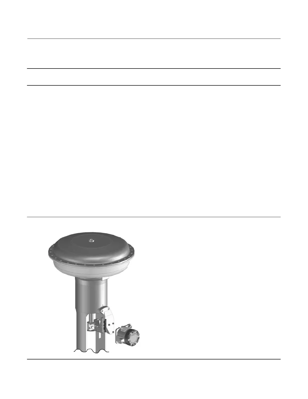
Sliding‐Stem Linear Actuators up to 210 mm (8.25 Inches) of Travel
The DVC6215 feedback unit has linkage‐less, non‐contact feedback on sliding‐stem actuators with up to 210 mm
(8.25 inches) travel. Figure 2‐9 shows a typical mounting on a sliding-stem actuator. For actuators with greater than
210 mm (8.25 inches) travel, see the guidelines on page 20.
1. Isolate the control valve from the process line pressure and release pressure from both sides of the valve body. Shut
off all pressure lines to the actuator, releasing all pressure from the actuator. Use lock‐out procedures to be sure
that the above measures stay in effect while you work on the equipment.
2. Attach the mounting bracket to the actuator.
Figure 2‐9. Mounting Parts for Sliding‐Stem Actuator with up to 210 mm (8.25 inches) Travel
X0127

 Loading...


