Instruction Manual
D103412X012
Principle of Operation
July 2013
259
Appendix A Principle of OperationA‐A‐
Digital Valve Controller Operation
The DVC6200f digital valve controller has a single module base that may be easily replaced in the field without
disconnecting field wiring or tubing. The master module contains the following submodules: current‐to‐pneumatic
(I/P) converter, printed wiring board assembly, and pneumatic relay. The relay position is detected by sensing the
magnet on the relay beam via a detector on the printed wiring board. This sensor is used for the minor loop feedback
(MLFB) reading. The master module can be rebuilt by replacing the submodules. See figures A‐1 and A‐2.
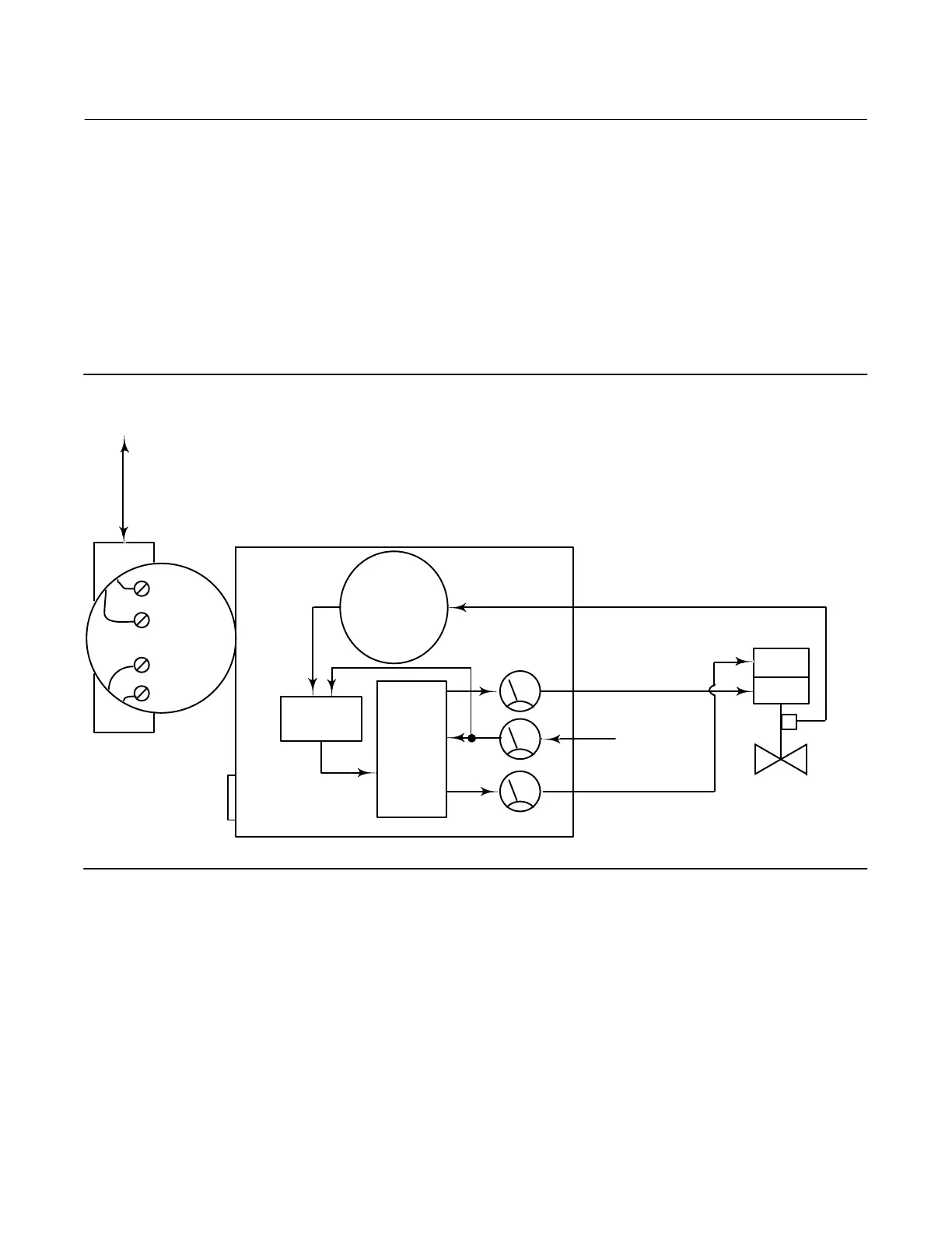
Figure A‐1. FIELDVUE DVC6200f Digital Valve Controller Block Diagram
E1376
DIGITAL
SETPOINT
9–32 VOLT
FIELDBUS
SUPPLY
PRESSURE
PRINTED
WIRING BOARD
PNEUMATIC
RELAY
I/P
CONVERTER
OUTPUT A
OUTPUT B
VALVE TRAVEL FEEDBACK
AUXILIARY
TERMINALS
TERMINAL BOX
DRIVE
SIGNAL
VALVE AND
ACTUATOR
VENT
The DVC6200f digital valve controller is a bus‐powered instrument that provides a control valve position in response
to a digital setpoint from the control room. The following describes a direct acting DVC6200f digital valve controller
mounted on a sliding-stem piston actuator, where the valve is closed with zero power to the instrument.
The setpoint is routed into the terminal box through a single pair of wires and then to the printed wiring board
assembly submodule where it is read by the microprocessor, processed by a digital algorithm, and converted into an
analog I/P drive signal.

 Loading...


