EasyManua.ls Logo

Fisher FIELDVUE DVC6200f User Manual

Fisher FIELDVUE DVC6200f
340 pages
To Next Page IconTo Next Page
To Previous Page IconTo Previous Page
Page #147 background imageLoading...
Page #147 background image
Instruction Manual
D103412X012
Detailed Setup—ISEL Function Block
July 2013
145
Input Selector Function Block
Overview
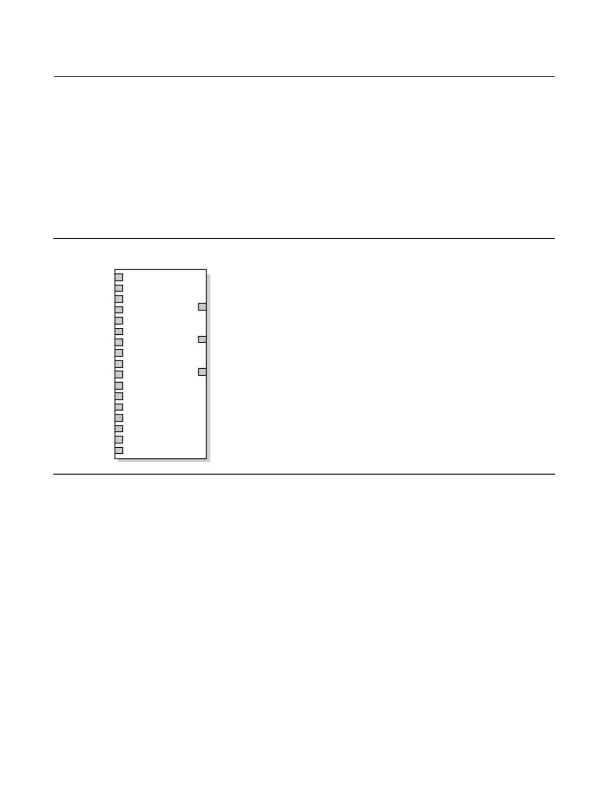
The Input Selector (ISEL) function block (figure 4‐12) can be used to select the first good, maximum, minimum,
average, or hot backup from as many as eight input values and place it at the output. The block supports signal status
propagation. There is no process alarm detection in the Input Selector function block. Figure 4‐13 illustrates the
internal components of the ISEL function block. Table 4‐40 lists the ISEL block parameters, their index numbers, and
descriptions.
Figure 4‐12. Input Selector Function Block
FIELDBUS_56A
SELECTED
OUT
IN_1
IN_2
IN_3
IN_4
DISABLE_5
DISABLE_6
DISABLE_7
DISABLE_8
OP_SELECT
IN (18)
=
Input used in the selection algorithm.
DISABLE (18) =
Discrete input used to enable or disable
the associated input channel.
OP_SELECT
=
Input used to override algorithm.
.
SELECTED
=
The selected channel number.
OUT
=
The block output and status.
OUT_D
=
Discrete output that signals
IN_5
IN_6
IN_7
IN_8
ISEL
OUT_D
DISABLE_1
DISABLE_2
DISABLE_3
DISABLE_4
a selected alarm condition.
Modes
The ISEL function block supports three modes of operation as defined by the MODE_BLK [5] parameter:
Manual (Man)—The block output (OUT [7]) may be entered manually.
Automatic (Auto)—OUT [7] reflects the selected input value.
Out of Service (OOS)—The block is not processed. The BLOCK_ERR [6] parameter shows Out of Service. In this
mode, you can make changes to all configurable parameters. The target mode of a block may be restricted to one
or more of the supported modes.
The Input Selector block Actual mode will be Out of Service if any of the following are true:
 The Actual mode of the resource block is not Auto
 The Input Selector block Target mode is Out of Service

Table of Contents

Question and Answer IconNeed help?

Do you have a question about the Fisher FIELDVUE DVC6200f and is the answer not in the manual?

Fisher FIELDVUE DVC6200f Specifications

General IconGeneral
ManufacturerFisher
CategoryController
ModelFIELDVUE DVC6200f
TypeDigital Valve Controller
Operating Temperature-40 to 85°C (-40 to 185°F)
Enclosure RatingNEMA 4X, IP66
Hazardous Area CertificationsATEX, IECEx, FM, CSA
Communication ProtocolFOUNDATION Fieldbus
Input Signal4-20 mA
Output Signal4-20 mA, digital signal
Supply Pressure1.4 to 6.0 bar (20 to 90 psig)
MountingDirect mounting on valve

Summary

Section 1 Introduction and Specifications

Specifications

Details the technical specifications and capabilities of the DVC6200f, including electrical and environmental data.

Section 2 Installation

Installation Procedures

Covers general installation procedures, including safety warnings and preparation steps.

Section 3 Basic Setup

Basic Setup Procedures

Outlines the essential procedures for initial setup and calibration of the instrument.

Device Setup

Guides through automatically setting up the instrument using actuator information and factory defaults.

Section 4 Detailed Setup

PlantWeb Alerts Setup

Guides on implementing PlantWeb alerts, including enabling and reporting configurations.

Section 5 Calibration

Calibration Procedures

Outlines the procedures for auto, manual, relay, and sensor calibration.

Auto Calibration

Explains the automatic procedure for calibrating the valve and actuator travel.

Manual Calibration

Details the manual procedure for calibrating valve travel points.

Section 7 Maintenance and Troubleshooting

Replacing the Magnetic Feedback Assembly

Details the steps for removing and replacing the magnetic feedback assembly.

Instrument Troubleshooting

Provides steps for initial troubleshooting of common instrument issues.

Table 7-2. Instrument Troubleshooting

Lists common symptoms, possible causes, and corrective actions for troubleshooting.

Section 8 Parts

Parts Ordering

Guides on how to order replacement parts and kits, including part numbers.

Appendix E Device Description Installation

Installing DD on a DeltaV ProfessionalPLUS Workstation

Provides general information on installing Device Descriptions (DDs) on a DeltaV system.

Appendix F Operating with a DeltaV System

Getting Started with DeltaV Host Systems

Lists initial steps and requirements for operating the DVC6200f with a DeltaV host system.

Using AMS Device Manager

Guides on accessing the digital valve controller configuration via AMS Device Manager.

Bringing the Device On-Line

Lists conditions and steps for completely configuring the digital valve controller in a fieldbus loop.

Setting up PlantWeb Alerts

Provides steps and considerations for implementing PlantWeb alerts within the DeltaV system.

Related product manuals