Installation Multi-DENCO
38 FläktGroup DC-2013-0101-GB • Subject to modifications • R5-08/2020
5.2 Substructures
5.2.1 Under unit drip tray
To protect the floor underneath a unit from any condensation, a drip tray can be
mounted underneath.
The drip tray can be used in a raised floor (underneath a base frame) or with a plinth.
It is designed to hold a small volume of water and should be used along with water
detection tape or spot sensor to prevent any significant build-up of water.
Fig. 5-1
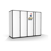
5.2.2 Base stand
For units to be used with a raised floor (upflow and downflow), a base stand should be
used underneath the close control unit. The height of the base stand can be from a min-
imum of 300 mm.
The base stand comes complete with adjustable feet (+/- 25 mm available). The sur-
face between the base stand and the unit should be lined with a 3 mm semi-hard gas-
ket. For more details or specification please contact your local sales representative.
For P-Version it is mandatory to be used with a raised floor as the secondary circuit is
located in the base stand where the minimum required height of the base stand is
600 mm.
For W-Version, the additional WaterCool module has a different basestand design.
This basestand is completed by connecting your raised floor pedestals to the sheet
metal frame. For advice on the compatibility of connecting your pedestal to basestand,
please see the technical drawing or contact your local FläktGroup support for details
or special requests.
Fig. 5-3
5.2.3 Support plinth
For units installed without a raised floor, a plinth should be used to allow for service
connections to the unit. The standard plinth is 200 mm tall and uses the same frame
and materials as the unit for a consistent look. Panels are removable the same as the
unit's panels.
The plinth of the W-Version must have the same height of the main unit plinth height
when both units stand beside each other and attached together.
Fig. 5-4
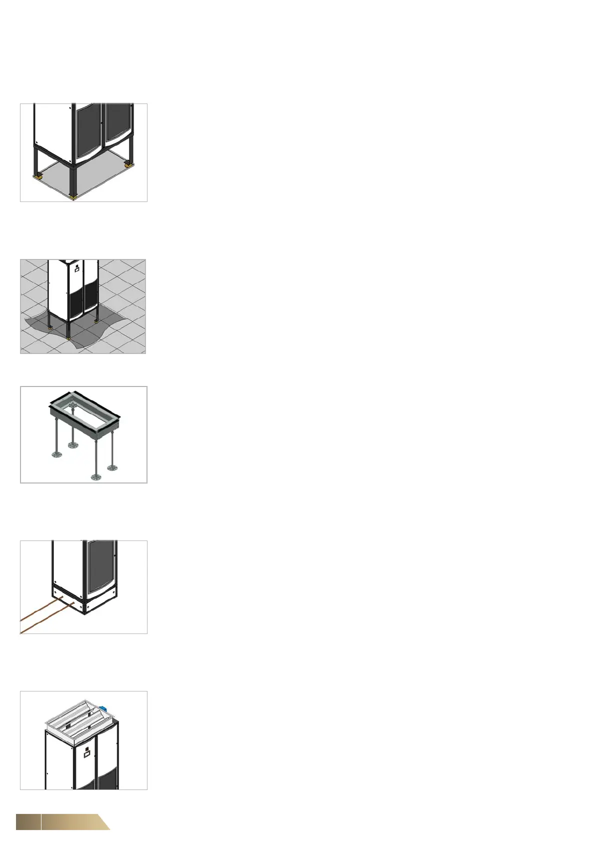
5.2.4 Shut off damper
Dampers can be provided loose for further installation on site. The control of the
damper is linked to the unit's C5-12 controller and can be made to open/close depend-
ing on the unit's operation. It can also close if a critical alarm in generated or linked to
fire alarm shutdown routines to protect your units.
Dampers should not be directly mounted to the air discharge of a fan. At least a
600 mm duct should be in between the damper and the fan.
Fig. 5-5