Electrical Connections Multi-DENCO
94 FläktGroup DC-2013-0101-GB • Subject to modifications • R5-08/2020
7.5 Customer terminals on C5-12 unit controller
Please refer to the wiring diagram and Controls manual for more details about connec-
tion to the controller or terminals.
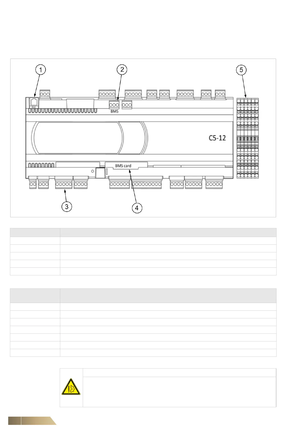
Fig. 7-7
Controller Description
1 Display connection for pGDX and pGD1 display
2 In build BMS RS485 Modbus connection
3 +VDC/GND/U1/U2 Air intake sensor, +VDC/GND/U3/U8 Air discharge sensor (optional)
4 BMS optional card - pCOWEB card (BACnet, SNMP, WEB, Modbus over IP connection) or pCONET (BACnet MSTP)
5 Customer Terminal Block
Customer terminal
block no.
Description
6 – 5 Remote On/Off for activating and deactivating the unit via a normally open volt free contact by others
3 – 5 Emergency Off, a volt free contact (supplied by others) opening, deactivates the unit (e.g. used in a fire alarm system)
10 – 11 The unit's critical alarm indication e.g. HP/LP, Airflow, High Temperature
12 – 13 The unit's maintenance alarm indication e.g. Dirty Filter, humidifier
17 – 5 Alarm contact of condensate pump (optional accessory)
100 – 101 Indication of unit’s operation (i.e. fans enabled)
+ / - / GND Unit’s network terminals for connecting multiple units to DencoNet or to remote display
Tab. 7-5
NOTICE
Wiring that is not isolated from active (live) components of non-SELV or non-
PELV circuits may induce power than can cause damage to control boards.
This may cause poor operation or system failure.
• Use double or reinforce insulation on electrical wiring external to the unit.