15
ARPEX 8706 en
Operating instructions 10/2017
1
1
øDA
2
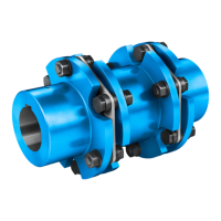
Fig. 4: Type with "H" module
1 Plate pack 2 "H" module
ARPEXturbo couplings are allsteel couplings and can be supplied, inter alia, in the types shown in
figures 3 and 4. The plate packs are arranged in the fitted coupling modules between the flanges of the
coupling parts and bolted to them alternately. The ARPEX coupling is torsionresistant and transmits the
torque without circumferential backlash. In axial and radial direction the coupling is however still flexible
and can absorb axial, radial and angular misalignment of the coupled units.
132
4
Fig. 5: Designs of the plates
1 6-sided plate ART/ARE-6 2 8-sided plate ART/ARE-8
3 10-sided plate ART/ARE-10 4 12-sided plate ART/ARE-12,
special version
The size designation of the coupling indicates the outside flange diameter DA (see fig. 3 and/or fig. 4) of
the coupling in mm. Attached item 6, 8, 10 or 12 (special version) specifies the number of
screwconnection points on the plate pack (see figure 5). This information is prefixed by a letter
combination specifying the component parts of the coupling.
Example: ART8 BVB 2208
Coupling with "B" module (B) "V"spacer (V) "B" module (B) of size 2208
from the ART8 series