48
ARPEX 8706 en
Operating instructions 10/2017
6.11 Demounting the intermediate unit
6.11.1 Procedure applying to modules with distance bush
Observe the safety instructions in section 6.1, "General information on fitting"!
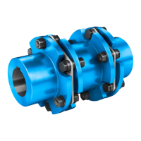
Reinsert the cheesehead bolts of the fastening (see figure 44). The design of the fastening is shown on
the orderspecific drawing of the coupling. Make sure that the cheesehead bolts are only inserted
loosely without being tightened.
Fig. 44: Inserting the cheesehead bolts of the fastening
Undo the screw connection of the flange (see figs. 6 to 16) and remove them.
WARNING
Serious injury
Risk of serious injury through falling coupling parts and/or flying fragments and/or risk of damage to the
coupling.
Secure all coupling parts against falling before undoing the screw connection.
Tighten the cheesehead bolts of the fastening, so that the plate packs are axially clinched to a dimension
of S1
fitting
(see table "Fitting data " on the orderspecific drawing of the coupling) and the intermediate
unit can be taken off (see figure 45).
S1 S1
fitting
Fig. 45: Illustration S1
fitting
WARNING
Risk of serious injury through flying fragments
Risk of serious injury through flying fragments and/or risk of damage to the coupling through the plate
packs being too tightly clinched during the fitting procedure.
The plate packs may be clinched to a maximum dimension of S1
fitting
(see figure 45) for fitting and
disassembly. The value in the table "Fitting data" on the orderspecific drawing of the coupling must be
adhered to.
If necessary, also shift the shaft ends of the machines to be joined together axially.
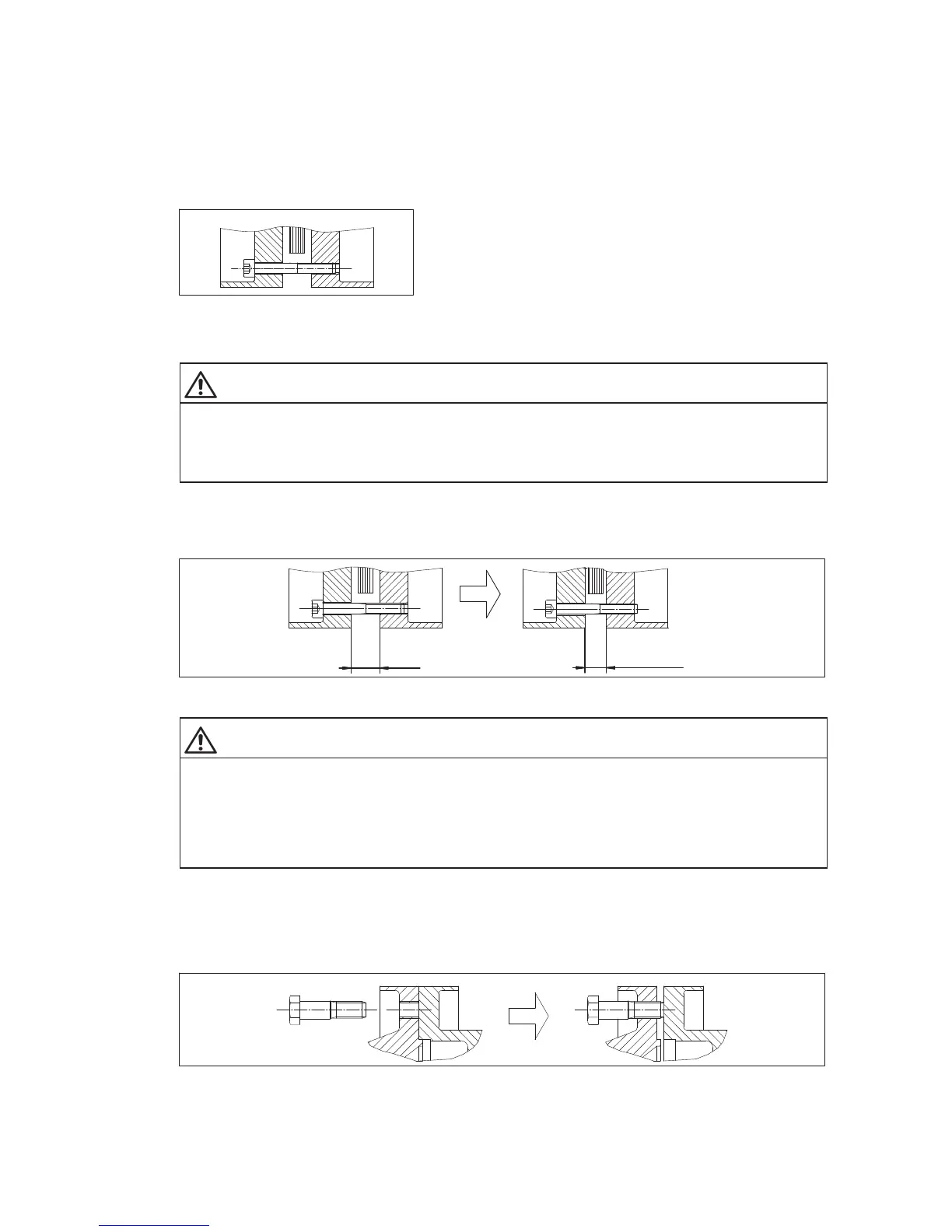
If necessary, using the hexagonsocket fitting bolts of the flange screw connection (see figures 6 to 16),
which must be screwed into the tapped holes provided for in the coupling parts, press the intermediate unit
(see figs. 6 to 16) out of the recess (centering pin) (see figure 46).
Fig. 46: Demounting the flange connection