32
ARPEX 8706 en
Operating instructions 10/2017
4 35512
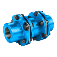
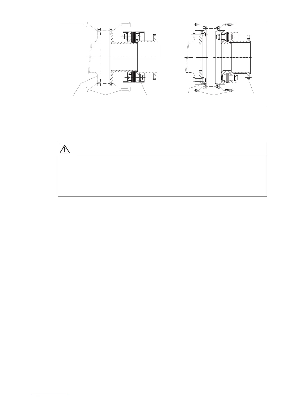
Fig. 22: Fitting "F" and "D" modules
1"D" module 2 "F" flange (fitted)
3"F" module 4 Connecting flange
5 Screw connection of flange
WARNING
Risk of serious injury through flying fragments
Risk of serious injury through flying fragments and/or risk of damage to the coupling.
– Locking nuts must only be used three times, to guarantee the locking properties.
– Adhere to specified tightening torques. Observe the instructions relating to cleaning and/or treatment
of the bolts with auxiliary materials.
6.5 Test run of the customer’s shaft with fitted coupling parts
Observe the safety instructions in section 6.1, "General information on fitting"!
If a test run of the customer’s shaft with fitted coupling parts and any weight simulators must be performed,
if necessary, this should be done in accordance with the configuration described in item 6.10.
6.6 Compensation of the flange or shaft distance "DBSE"
Observe the safety instructions in section 6.1, "General information on fitting"!
"DBSE" = distance between shaft ends
Set the flange or shaft distance between the machines to be coupled exactly to the fitting
dimension "DBSE" (on axially pretensioned couplings "DBSE fitting"), as shown on the orderspecific
drawing of the coupling.
Lengths can be adjusted with shims. These are mainly used with tapering shaft ends and customer’s
connecting flanges. Shims form only an optional part of the scope of delivery. The position of the shims can
be seen on the orderspecific drawing of the coupling. As a rule, they are fitted between the fitted
coupling part (e.g. "M"hub or "B" module, see figure 23) and the intermediate unit (e.g. "H" module or
"V" spacer, see figure 23). With customer’s connecting flanges they can also be fitted between the fitted
coupling part (e.g. "F" flange, see figure 23) and the customer’s flange.