33
ARPEX 8706 en
Operating instructions 10/2017
123 514
176
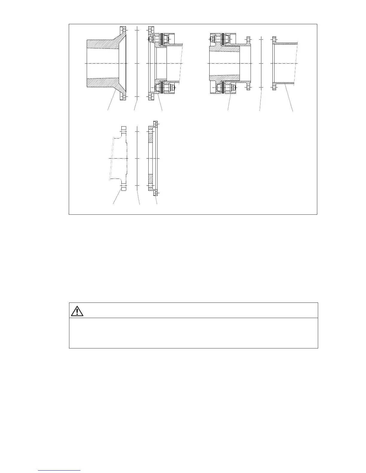
Fig. 23: Fitting shims
(Shims, basic illustration: "X" module identical with "B" module)
1 Shims 2 "M" hub
3"H" module 4 "B" module
5"V"-spacer 6 Connecting flange
7"F" flange
The number of shims to be used can be found on the orderspecific drawing of the coupling (see table
"Fitting data"). The normal dimension is reached with half the delivered shims. The shims are pushed onto
the "recesses" (centering pin) of the connecting flanges before fitting the screw connections of the flanges.
WARNING
WARNING
Risk of serious injury through flying fragments
Risk of serious injury through flying fragments and/or risk of damage to the coupling.
The maximum number of shims to be used per "recess" (centering pin) must not be exceeded (see table
"Fitting data" on the orderspecific drawing of the coupling).