35
ARPEX 8706 en
Operating instructions 10/2017
6.8 Fitting the intermediate unit
Observe the safety instructions in section 6.1, "General information on fitting"!
• Clean the surfaces to be joined; they must be absolutely clean and greasefree.
CAUTION
Risk of corrosion burns through chemical substances
Avoid burns when working with corrosive cleaning agents.
Observe manufacturer’s instructions for handling cleaning agents and solvents.
Wear suitable personal protective equipment (gloves, safety glasses).
6.8.1 Procedure applying to modules with distance bush
Observe the safety instructions in section 6.1, "General information on fitting"!
The design of the fastening is shown on the orderspecific drawing of the coupling.
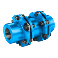
Unscrew the cheesehead bolts (pos. 1, figure 25) of the fastening and remove the distance bushes
(pos. 2, figure 25).
1
2
1
Fig. 25: Removing the distance bush from the fastening
1 Cheese-head bolt 2 Distance bush
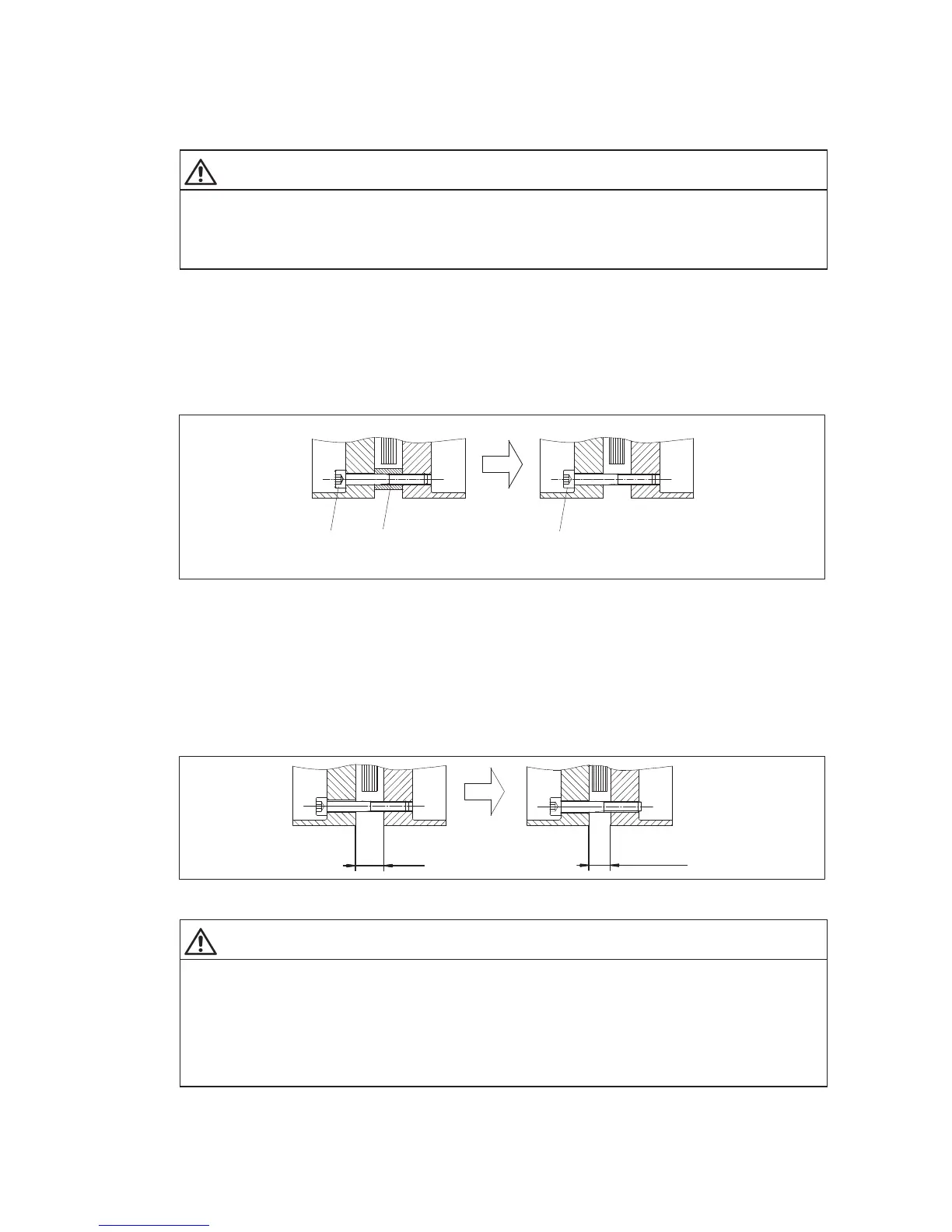
Screw in the cheesehead bolts of the fastening again. The plate packs of the fitted modules (e.g. "B"
module, "D" module or "F" module, see figs. 6 to 16) or the intermediate unit ("H"
module, "W" module
or "F" module (see figures 6 to 16) must be axially clinched to a dimension of S1
fitting
(see table "Fitting
data" on the orderspecific drawing of the coupling). The intermediate unit ("H" module, "W" module,
"F" module or "V" spacer (see figures 6 to 16)) must fit between the fitted coupling parts or the customer’s
connecting flanges (see figure 28, figure 29 and figure 30).
S1
fitting
S1
Fig. 26: Illustration S1
fitting
WARNING
Risk of serious injury through flying fragments
Risk of serious injury through flying fragments and/or risk of damage to the coupling through the plate
packs being too tightly clinched during the fitting procedure
The plate packs may be clinched to a maximum dimension of S1
fitting
(see figure 26) for fitting and
disassembly. The value in the table "Fitting data" on the orderspecific drawing of the coupling must be
adhered to.
The instructions relating to the assemblybalanced couplings in item 6.7 must be observed.