38
ARPEX 8706 en
Operating instructions 10/2017
With single and twopart coupling versions with single or twoside customer’s coupling flange
(see e.g. type MH in figure 30) the intermediate unit is fitted between a fitted coupling part and a customer’s
connecting flange or between two connecting flanges of the customer.
1
3
2
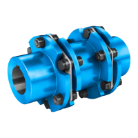
Fig. 30: Twopiece coupling version MH with customer’s connecting flange on one side
1"M" hub (fitted coupling part) 2 "H" module (intermediate unit)
3 Customer’s flange
Insert the screw connection of the flange (see figs. 6 to 16) and tighten only handtight.
The design of the fastening is shown on the orderspecific drawing of the coupling.
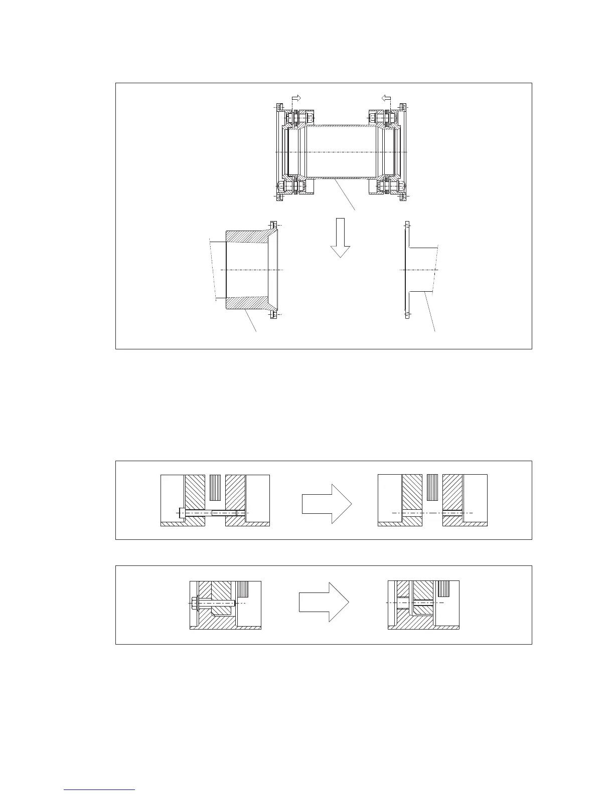
Remove the bolts from the fastening (see figure 31 or figure 32).
Fig. 31: Removing the fastening in case of distance bush
Fig. 32: Removing the fastening in case of threaded bush
Tighten the screw connection of the flange gradually one after the other to the prescribed tightening torque
(for tightening torque, see orderspecific drawing of the coupling).