Flowserve Pump Division - 10
SECTION III: Installation
GENERAL
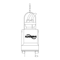
Use the lifting bail bolted to the motor for handling the pumping unit. Exercise care in slinging and
handling the unit. Observe the minimum cable bending radius given below.
CAUTION: THE COOLING FLUID LEVEL AND QUALITY IN THE MOTOR MUST BE CHECKED
BEFORE THE UNIT IS OPERATED; see Section III, Motor Filling.
CAUTION: FLOWSERVE PUMP DIVISION RECOMMENDS THAT THE MOTOR WINDING
INSULATION BE CHECKED ONCE THE UNIT IS IN PLACE AND PRIOR TO
APPLYING POWER TO THE UNIT; see Section III, Insulation Testing.
POWER CABLE
Pay special attention to the power supply cables during installation. Where the power supply cables are
subject to chafing and vibration, fasten them in wooden blocks or protect them by means of cable guards.
CAUTION: DO NOT BEND THE CABLE TO A RADIUS BELOW 4 TIMES THE CABLE
DIAMETER.
CAUTION: DO NOT LIFT THE UNIT BY THE POWER CABLES.
CAUTION: PER ANSI/NFPA 70 (NEC) SECTION 400-9, POWER CABLES MAY NOT BE
SPLICED DURING INITIAL INSTALLATION. SPLICES FOR NON-EXPLOSION
PROOF MOTORS OCCURRING AFTER INITIAL INSTALLATION MUST CONFORM
TO ANSI/NFPA 70 400-9.
CAUTION: POWER CABLES FOR MOTORS CERTIFIED AS EXPLOSION PROOF PER
ANSI/NFPA 70 MUST BE CONTINUOUS PER SECTION 501-11. NO CABLE
SPLICES ARE PERMITTED.
CAUTION: POWER CABLES ARE TO BE REPLACED ONLY WITH AN APPROVED POWER
CABLE PURCHASED FROM FLOWSERVE PUMP DIVISION. POWER CORD
REPLACEMENT WITH A NON-APPROVED POWER CABLE WILL VOID THE
FACTORY WARRANTY AND NEGATE THE EXPLOSION PROOF CERTIFICATION.
LOCATION OF EQUIPMENT
The pump should be located to allow an overhead crane or lifting device with sufficient capacity to lift the
entire unit. In wet pit applications, the suction eye of the pump must be located far enough above the
bottom of the wet pit to allow for the maximum rated solid size to pass under the pump; i.e., a pump rated
for 4-inch (100 mm) solids must have at least a 4-inch (100 mm) clearance between the bottom of the well
and the suction eye of the pump.
SITE PREPARATION
Flowserve Pump Division MSX Series 2 wet well pumps can be installed in a permanent well via a guide
rail system or on a pedestal base so that they are transportable. Series 2 pumps can also be installed in
dry pit applications with the use of a suction base and permanent discharge piping.
Foundation
The foundation should be of sufficient strength to absorb vibration (i.e., at least five times the weight of
the pump unit) and to form a permanent, rigid support for the suction base. A concrete foundation on a
solid base should be satisfactory.
Pump manufacturers can calculate, or determine by test, the natural frequency of the pump assembly,
including pump and driver. However, in a field installation, the vibrating structure comprises, in addition to
the pump assembly, the foundation, the mounting, the piping and supports. The natural frequency of the
vibrating structure is determined by the stiffness of the total structure and by its equivalent mass. The