Flowserve Pump Division - 15
FLOAT SWITCHES
In wet pit applications, customer supplied float switches are typically used to control the starting and
stopping of the pump(s) based on the fluid level of the well. The switches hang freely from a bracket
mounted to the frame of the wet well. The float switches should be located such that they will not tangle
with each other or with the discharge piping. Either of these situations may give erroneous signals.
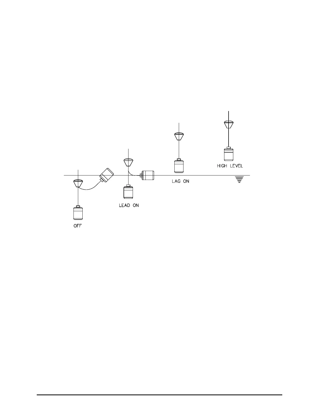
A typical arrangement for a float switch control system for a wet well is shown in Figure 4: Float Switch
Installation. The four switches are as follows: 1) Pump(s) off; 2) Lead pump on; 3) Lag pump on (for
arrangements with two or more pumps); 4) High level alarm. There could be additional lag pump
switches depending on the number of pumps in the system.
CAUTION: THE SYSTEM SHOULD BE DESIGNED TO MINIMIZE THE NUMBER OF STARTS.
THE FREQUENCY OF RESTARTS SHOULD NOT EXCEED RECOMMENDATIONS BY
NEMA MG-10, TABLE 7.
Figure 4: Float Switch Installation
ELECTRICAL
CAUTION: FOLLOW LOCAL PRACTICES AND THE NATIONAL ELECTRIC CODE WHEN
CONNECTING EQUIPMENT.
Motor Power Wiring
Electrical power is supplied to the motor through the power supply cable(s) leading out of the pump
junction box. Each motor is supplied with standard 35 foot (10.5 m) power cable(s) (50, 75 and 100 foot
cables are also available). The motor rated voltage can be found on the pump/motor nameplate. Motor
voltage for dual power motors can be found on the label on the junction box. The motor is connected to
the power cable(s) at the factory according to Figure 5: Motor Connection Diagram. Installation and
operation instructions for power service at other voltages may vary from those listed in this manual.
Contact Flowserve Pump Division directly for variations in installation and performance at other voltages.
Most Series 2 MSX Pumps are furnished multiple power cables to meet the ampacity ratings as required
by ANSI/NFPA 70 (NEC). Multiple power cables must always be connected in parallel such that all the
White (W) power leads are connected to the same phase (example T1) at the control panel terminal
block; and likewise, all the Red (R) power leads are connected to a unique phase (T2), and all the Black
(B) power leads are connected to a unique phase (T3).
Note that some MSX pumps will also have a separate cable for control wires. Control cables will always
have conductors of a smaller wire size (AWG) than power cables. Refer to supplemental instructions for
specific wiring instructions as applicable.