Flowserve Pump Division - 22
Complete Overhauls
Frequency of a complete overhaul depends upon the hours of operation of the pump, the severity of the
conditions of service, the materials used in the pumping unit construction, and the care the pump receives
in operation.
Do not open your unit for inspection unless there is definite evidence that the capacity has fallen off
excessively or unless there is indication of trouble inside the pump or the motor.
PUMP DISMANTLING PROCEDURE
Care must be exercised in the dismantling operation. For convenience at re-assembly, lay out all parts in
the order in which they are removed matchmarking to disassembly. Protect all machined faces against
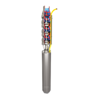
metal to metal contact and corrosion. Proceed as follows; reference Motor/Pump Sectional Drawing.
Impeller and Casing
1. Disconnect power from the motor. Use lifting bail and chain to remove the pump from
wet pit.
2. Transport pump to a Flowserve Pump Division approved service shop.
CAUTION: TAKE PRECAUTIONS TO PROTECT THE PUMP DURING TRANSPORTATION.
3. Remove bolts holding the adapter plate to the pump casing. Draw out the pump rotating
assembly complete with the motor. Set the motor on a mounting stage or wooden vee-
blocks. Care must be taken in handling the unit.
CAUTION: DO NOT REMOVE THE BOLTS THAT HOLD THE BEARING HOUSING TO THE
ADAPTER PLATE AS THIS MAY LEAK COOLING FLUID, AND COULD DAMAGE
THE MECHANICAL SEAL.
4. Drain fluid from the cooling system.
5. Remove the impeller mounting screw. The screw was mounting using Loctite 2760 and
may require heating to 400° F (204° C) for removal.
6. Remove the impeller and the impeller key. Note that upon removal of the impeller, the
lower mechanical seal will be disengaged and residual cooling fluid may leak from the
bearing housing.
7. Remove the wear ring(s) as necessary. Reference maintenance of wearing rings
(refer to page 23).
Bearing Housing
1. Drain cooling fluid from bearing housing.
2. Remove primary ring (rotating face) of the lower mechanical seal from the shaft.
3. The heat exchanger plate can be removed by removing the snap ring and using
screwdrivers to gently pry from the groove at the outside diameter of the plate.
CAUTION: DO NOT REMOVE THE HEAT EXCHANGER PLATE FROM THE ADAPTER PLATE
UNLESS THERE IS REASON TO BELIEVE THAT THE COOLING SYSTEM IS NOT
FUNCTIONING PROPERLY.
CAUTION: THE HEAT EXCHANGER PLATE IS PART OF A PRESSURE VESSEL CONTAINING
THE COOLING FLUID. THE O-RINGS MUST BE REPLACED ANY TIME THIS PART
IS REMOVED FROM THE ADAPTER PLATE. THE O-RING GROOVES SHOULD BE
INSPECTED TO ASSURE THAT THE PLATE SEALS PROPERLY.
4. Remove the adapter plate from the bearing housing. Take care not to damage the
mating ring while removing the adapter plate. The mating ring (stationary face) of the
mechanical seal should not be removed unless it is being replaced.
5. Remove the oil impeller by removing the set screw on its hub.
6. Remove the cooling fluid impeller cover plate.