5100 Series
Section
2
Operating
Instructions
2-1.
INTRODUCTION
2-2.
This section contains information regarding
installation and operation
of
the Model 5100 Series
Calibrators, It is recommended the contents of
this
section be read and understood before any attempt
is
made to operate the instrument. Should any
difficulties
arise
during operation,
contact your nearest
John
Fluke
Sales Representative, or the
John Fluke Mfg. Co,,
P.O.
Box
43210,
Mountlake Terrace,
WA
98043;
telephone
(206)
774-2211.
A list
of
sales
representatives is located
in.
Section 7 of the Instruction
Manaual.
2-3.
SHIPPING INFORMATION
2-4.
The instrument is packed and shipped in
a
foam-
packed cardboard carton, if reshipment is required use
the
original
container or req uest a new container from the
John Fluke Mfg.
Co.,
Inc.
Please
include the instrument
Model number with your request.
2-5.
OPTIONS
AND ACCESSORIES
2-6.
Listed in Table
2-1
are the options and accesor-
ies available for the 5100 Series Calibrators. A detailed
description of each is included in Section 6 of the Inst-
ruction Manual.
2-7.
INSTALLATION
2-8.
The 5
1
00 instruments
are
designed
for bench-top
use (all) or for installation
in
a
standard
19-inch
equipment rack
(5
100A and 5 101 A) using the optional
accessory rack mounting kit. If desired, accessory chassis
slides
may be installed to facilitate access to the rack-
installed equipment.
Information
on the installation of
rack mounting accessories
is
given in Section
6 of the
Instruction Manual.
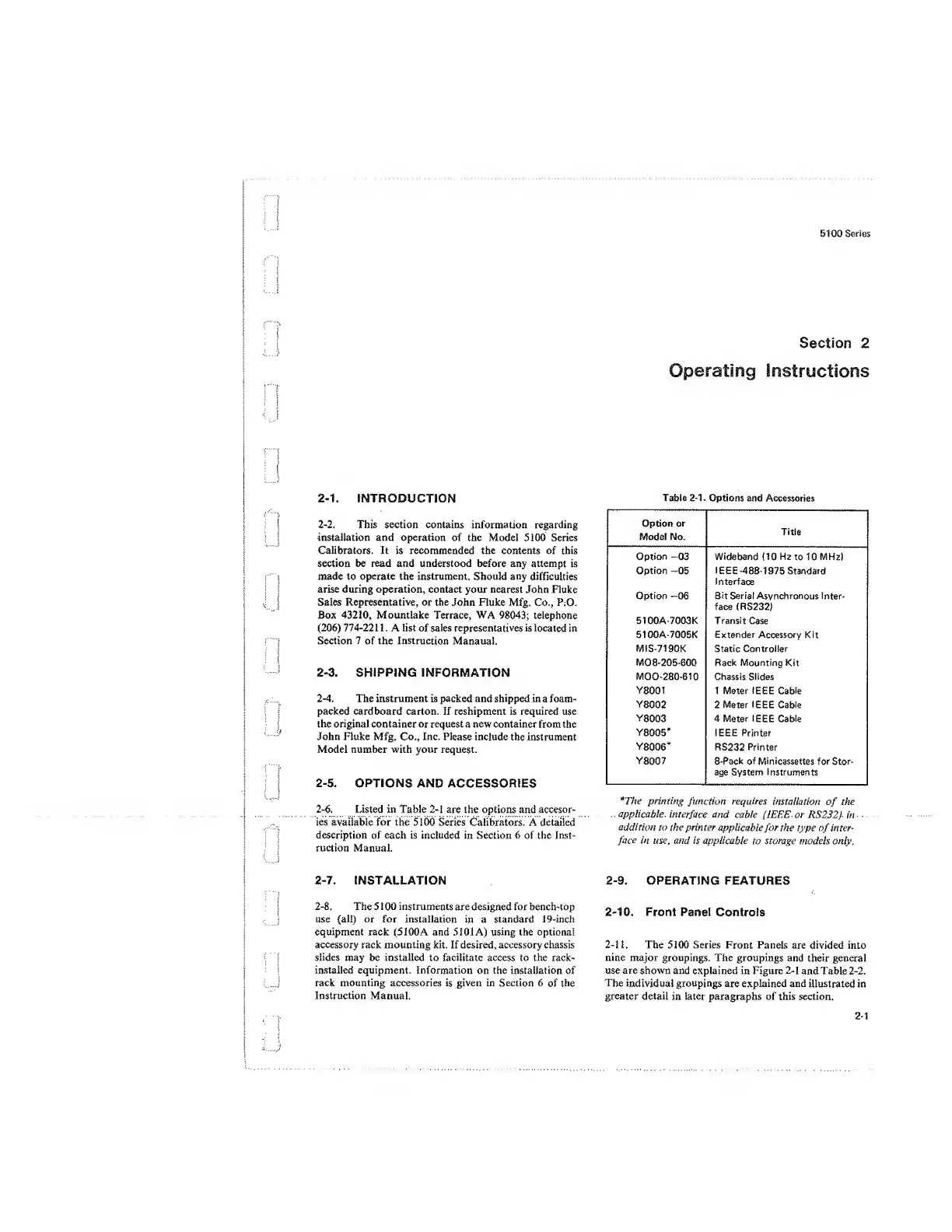
Table
2-1-
Options and
Accessories
Option
or
Model No.
Title
Option
-03
Wideband
(10
Ha to 10 MHz)
Option
—05
IEEE -488-1975
Standard
Interface
Option
—06
Sit
Serial Asynchronous Inter-
face { RS232)
510GA-7003K Transit Case
51GGA-7005K Extender Accessory Kit
M1S-7190K Static Controller
MO
8-
205-600
Rack Mounting Kit
MOO-28G-610 Chassis Slides
Y8001
1 Meter IEEE Cable
Y8002
2 Meter
IEEE
Cable
Y8003
4 Meter
IEEE
Cable
Y8005*
IEEE Printer
Y8006*
RS232
Printer
Y8007
8-Pack of Minicassettes
for Stor-
age System Instruments
*The
printing
function
requires
installation
of
the
applicable
interface and
cable lIEEE or
US
232)
in
addition
to the printer
applicable
for the type of inter-
face
in use, and
is
applicable
to
storage
models only.
2-9.
OPERATING FEATURES
2-10.
Front Panel
Controls
2-11.
The 5100 Series
Front Panels
are divided into
nine major groupings. The groupings
and their general
use are shown and explained in Figure
2-1
and
Table
2-2.
The
individual groupings are explained and
illustrated
in
greater
detail in later paragraphs of this section.
2-1
 Loading...


