5100 Series
results in a Err3 or
Err4
an erroneous output
value results
from the
programmed
fraction. Programming
a valid
output
or resetting
the instrument will
remove
the error.
The
procedure
in the following example
demonstrates
how
the
percentage of error is computed
on a 12 volt base
rather
than on a 9 volt output
obtained
with the
3/4
fractional scale entry. The
fractional
scale feature cannot
be used when the instrument is in
the Keyboard mode.
j.
Obtain an output of 12
volts using the DC
volts output.
2. Depress
the Data
Entry Group keyswitches
“3
,/,4” to make the fractional scale entry.
3. The Central Display
shows
"3/4".
4. Depress
the ENTER keyswitch.
5. The Central Display blanks and
the Output
Display is altered to read +9.0000
volts.
6. Rotate the EDIT
switch
clockwise for an Output
Display of
+9.0001.
7. The
Central Display
reads
-.0008
and the
%ERROR
indicator is
illuminated.
NOTE
A change
of
.0001 at 9 volts base would
read
-.0011
(0.0001
19
=
-.0011%) while the
same
change with a 12
volt
base
would
read the
-.0008
displayed.
2-90.
Entries can
be made
for any function except
dBm or ohms. The
entries may also be altered by making
a new
fractional
scale entry. For example: Using the
above example
if
1/2
was entered the
output display
would
change
to
6.0000,
1 /
4 would change it to 3.000
and
1/1
would
change it back to 12.000. As you
can see all
entries have made their change gased on the
original 12
volts, not on the current output. If at
some
time during
the procedure it is desired to change
the base to the
current output it can be accomplished by
depressing the
NEW REF/ CAL 1
OHM keyswitch.
If the ENTER
switch is depressed
without
entering a valid fraction, the
instrument drops out
of the fractional scale mode.
2-91.
External Oscillator
Operation
2-92.
Desired frequencies that
are
outside the capa-
bility of the instrument, i.e.,
more than one significant
digit or more accurate,
can
be obtained using the Exter-
nal Oscillator feature.
The
external frequency must be
within the range of
the standard
5100 Series
(50
Hz to
50
kHz) at I.2V rms +/-
5%
and an output
impedance
no greater than 50 ohms. The signal is input
to the
instrument at pins
4
(EXT OSC) and
7
(OSC
COM)
of
J2, the Analog
Connector on
the Rear Panel.
Instruments
with serial
numbers less than 855000 will
have pin 14 as
OSC
COM.
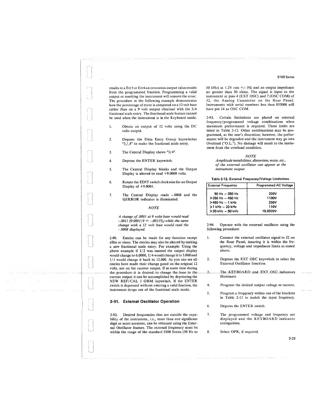
2-93. Certain limitations are placed on external
frequency/ programmed voltage combinations
when
maximum performance is required. These
limits
are
listed in Table
2-12.
Other
combinations
may
be
pro-
grammed, at the user’s discretion;
however, the
perfor-
mance will be degraded and the instrument
may
go into
Overload (“O.L.”). No damage
will
result to
the instru-
ment from the overload condition.
NOTE
Amplitude instabilities, distortion,
noise,
etc.,
of
the external
oscillator can appear at
the
instrument output.
Table
2-12.
External
Frequency/Voltage
Limitations
External
Frequency
Programmed AC Voltage
50 Hz
-
350 Hz
250V
>350 Hz -450 Hz 1100V
>450 Hz -1
kHz
250V
>1 kHz
-20
kHz 110V
>20 kHz
-50
kHz
19.9999V
2-94.
Operate with the external oscillator using the
following procedure:
1. Connect the
external
oscillator signal to J2 on
the
Rear
Panel, insuring it is within the fre-
quency,
voltage
and
impedance limits as stated
above.
2. Depress the
EXT
OSC
keyswitch to select the
External Oscillator function.
3.
The
KEYBOARD
and
EXT
OSC
indicators
illuminate.
4.
Program the
desired
output voltage or current.
5. Program
a
frequency
within one of the brackets
in Table
2-13
to match the input frequency.
6. Depress the
ENTER
switch.
7. The programmed
voltage
and frequency are
displayed and
the KEYBOARD indicator
extinguishes.
8. Select OPR, if required.
2-23
 Loading...


