5100
Series
2-126.
Initiation
Characters
2-127.
RESET
2-128.
The
instrument is reset to the initial
sequence
and local mode
with this instruction. It
assumes
the
default
condition, i.e., all registers reset.
The
visible effect
on
the instrument is the
STDBY, LOCAL,
INT
and 50D
DIVIDER
indicators
illuminated and the Output Dis-
play
set to 0.0000
mV dc. In addition the
Wideband,
External
Oscillator, Echo
Capability
and
Line Feed
Suppression features are disabled and
the IEEE Service
Request disabled.
NOTE
Allow a 500 ms
interval
between
a Reset
command"*” and any
subsequent
command,
2-129.
CLEAR “C”
2-130.
A Single
“C”
entry during a numeric entry
while
in the keyboard
mode
dears that entry.
A
second succes-
sive
“C”
entry
clears
the instrument to its
initial
state
except
it remains
in remote. When the
“C”
is directly
preceded by
an “L”
entry
the programmed
entry
limits
are set to their
maximum settings. The
entry
“TC’sets
the
tolerance
limits
to
maximum tolerance.
2-
131,
INTERFACE
INTERRUPT
ENABLE
CODES
3-
132. Interrupts for the
interface
system are generated
using the alpha
character
I followed by an octal number
between 0 and
3,
inclusive. The numeric is based
on
the
three binary
bits of an octal number with bit 0
high if the
interrupt
(Service Request SRQ in the
IEEE
interface) is
enabled
with
a “Ready” and bit 1 high if
enabled with an
“Error”.
“Ready”
interrupt
refers to a SRQ
at the end of a
timeout
which represents the
maximum
settling time
required in the programmed range.
They are generated
after a command
which causes a
change in output,
e.g., a
terminator or
Standby/
Operate command. Bit 2
is not
used at this time so
the
available codes extend only to
an
octal 3. The possible
combinations are given in Table
2-
15.
Table
2-15.
Interface Interrupt Codes
Numeric
Interrupt
On
Ready
Error
0 Disabled
Disabled
1 Enabled
Disabled
2 Disabled Enabled
3 Enabled Enabled
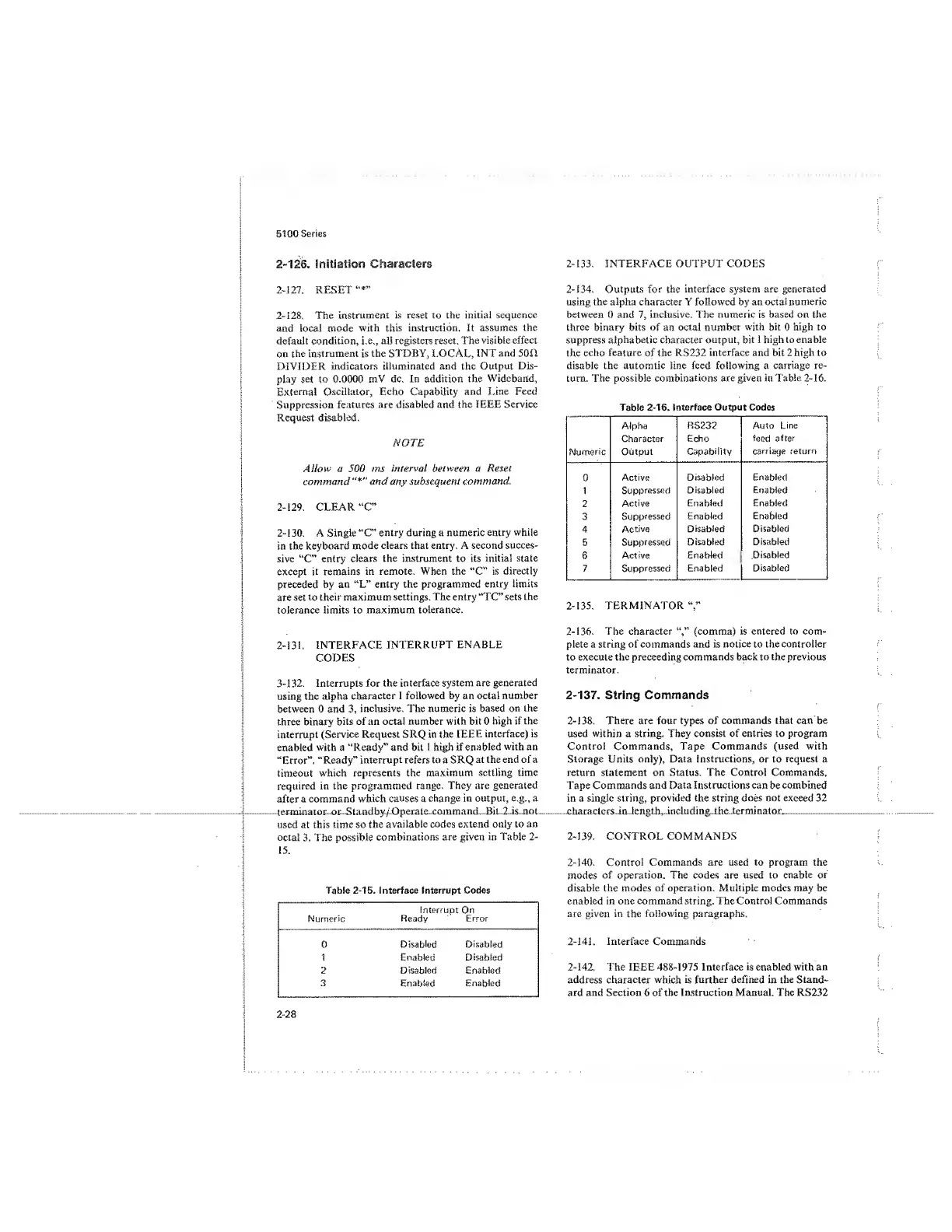
2-133.
INTERFACE OUTPUT CODES
2-134.
Outputs
for the
interface system are generated
using the alpha character Y followed by an octal numeric
between 0 and
7,
inclusive. The numeric is based on the
three binary bits of an octal number
with
bit
0
high to
suppress
alphabetic character
output, bit 1 high to enable
the
echo
feature
of
the RS232
interface and bit 2 high to
disable the automtic tine feed following a carriage re-
turn. The possible
combinations
are
given
in
Table
2-16.
Table
2-16. Interface Output Codes
Numeric
Alpha
Character
Output
RS232
Echo
Capability
Auto Line
feed
after
carriage return
0
Active Disabled Enabled
1
Suppressed
Disabled Enabled
2
Active
Enabled Enabled
3
Suppressed
Enabled Enabled
4
Active
Disabled Disabled
5
Suppressed
Disabled
Disabled
6
Active
Enabled Disabled
7 Suppressed
Enabled
Disabled
2-135.
TERMINATOR
2-136. The character (comma) is entered to
com-
plete a string of commands and is
notice
to the controller
to execute the preceeding commands back to
the
previous
terminator.
2-137.
Siring Commands
2-138.
There are
four
types of
commands
that can
be
used
within
a
string.
They
consist of entries to program
Control Commands,
Tape Commands (used with
Storage Units only), Data Instructions, or to request a
return statement on Status. The Control Commands,
Tape Commands and Data Inst ructions can be combined
in a single string, provided the string does not exceed 32
characters in length,
including
the
terminator.
2-139. CONTROL COMMANDS
2-140.
Control
Commands are used to program the
modes
of operation. The codes are used to enable or
disable
the modes of operation. Multiple modes may be
enabled in one command string. The Control Commands
are given in the following paragraphs.
2-141.
Interface Commands
2-142.
The
IEEE
488-1975 Interface is enabled with an
address
character which is
further defined in the Stand-
ard and Section
6
of the Instruction Manual. The RS232
2-28
 Loading...


