5100 Series
"locked
out”
by a
remote
command it can return the
instrument to local
operation
by toggling the REMOTE
switch on the front panel.
2-125.
Programming
instructions
may be either
initia-
tion or string commands. The
initiation commands
are
one or two character messages that are
operated
on as
soon as they
arrive unless they are part of a string, in
which case they are executed in sequence within the
string. The only exception is reset, which has an imme-
diate response. String commands can be Control Com-
mands, Storage Commands (used with the 5101 A only),
Data Instructions, Status requests or a combination of
the first three, and are sent in a series
of one
to
thirty-two
characters that are, with the exceptions
noted
in the
text, concluded with a terminator character.
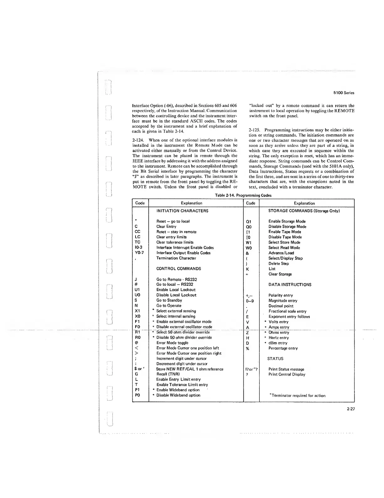
Table
2-14.
Programming Codes
Code Explanation
Code Explanation
INITIATION
CHARACTERS
STORAGE COMMANDS
(Storage Only)
*
Reset -
go to
focal
Q1
Enable
Storage Mode
C
Clear Entry
Q0
Disable Storage
Mode
cc
Reset
—
stay
in remote
[1
Enable
Tape Mode
LC
Clear entry limits
[0
Disable Tape Mode
TC
Clear tolerance
limits
W1
Select Store
Mode
10-3
interface interrupt
Enable Codes
wo
Select Read
Mode
YO-7
Interface
Output
Enable
Codes
&
Advance/Load
Termination Character
(
Select/Display
Step
}
Delete Step
CONTROL
COMMANDS
K
List
=
Clear Storage
J Go
to
Remote
-
RS232
#
Go to local
—
RS232
DATA INSTRUCTIONS
U1
Enable Local Lockout
uo Disable Local Lockout
+
-
Polarity entry
s Go
to Standby
0-9
Magnitude
entry
N Go to
Operate
Decimal
point
XI
*
Select external sensing
/
Fractional scale
entry
XO
*
Select
interna!
sensing
E
Exponent entry
follows
FI
*
Enable external oscillator mode
V
*
Volts entry
F0
*
Disable external oscillator
mode
A
*
Amps
entry
R1
*
Select 50 ohm
divider
override
Z
*
Ohms entry
R0
*
Disable
50
ohm divider
override
H
*
Hertz entry
Error
Mode
toggle
D
*
dBm
entry
<
Error
Mode Cursor one position left
%
Percentage entry
> Error Mode Cursor one position right
;
Increment
digit under cursor
STATUS
Decrement digit under cursor
$
or
'
Store NEW REF/CAL 1 ohm reference
Dor"?
Print Status
message
G
Recall (TNR)
?
Print
Central Display
L Enable
Entry
Limit entry
T Enable Tolerance Limit entry
PI
*
Enable
Wideband
option
P0
*
Disable Wideband
option
’Terminator
required for action
Interface Option
(-06),
described in
Sections
605
and
606
respectively, of the Instruction Manual. Communication
between the controlling device and the instrument inter-
face must be in the standard ASCII codes. The codes
accepted by the instrument and a brief explanation of
each is given in Table
2-14.
2-124.
When one of the
optional interface modules is
installed in the
instrument
the Remote Mode can be
activated either
manually
or from the Control Device.
The
instrument can be
placed in remote through the
IEEE interface by
addressing
it with the address assigned
to the instrument.
Remote can be accomplished through
the
Bit
Serial
interface by programming the character
“J”
as described in later paragraphs. The instrument
is
put in remote from the front panel by toggling the
RE-
MOTE switch. Unless the front
panel is
disabled or
2-27
 Loading...


