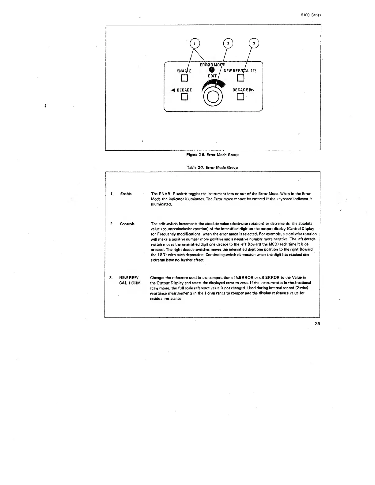
Figure
2-6.
Error Mode Group
Table
2-7.
Error Mode Group
1. Enable The ENABLE switch toggles the instrument into or
out of the
Error Mode. When in the Error
Mode
the indicator illuminates. The Error mode cannot be
entered
if
the keyboard
indicator
is
illuminated.
2. Controls The
edit switch
increments the absolute vaiue
(clockwise rotation) or
decrements the absolute
value
(counterclockwise
rotation) of
the
intensified digit on the output
display
(Central Display
for Frequency modifications) when the error mode is selected.
For
example, a
clockwise rotation
wii! make a positive
number more
positive
and a
negative number more
negative. The left
decade
switch
moves the intensified
digit one
decade
to
the
left
(toward the MSD) each
time
it is
de-
pressed.
The right decade
switches
moves the
intensified digit one position to the right (toward
the LSD) with each
depression. Continuing switch
depression when the digit has reached one
extreme have no
further effect.
3. NEW REF/
CALI ©MM
Changes the reference used
in the
computation
of %ERROR
or
dB
ERROR to the Value
in
the Output
Display and
resets the displayed error to zero.
If
the
instrument
is
in
the
fractional
scale
mode,
the full scaie
reference
vaiue
is
not changed.
Used
during internal sensed
(2-wire)
resistance
measurements in the 1 ohm range to compensate the
display
resistance
vaiue for
residua! resistance.
 Loading...


