5100
Series
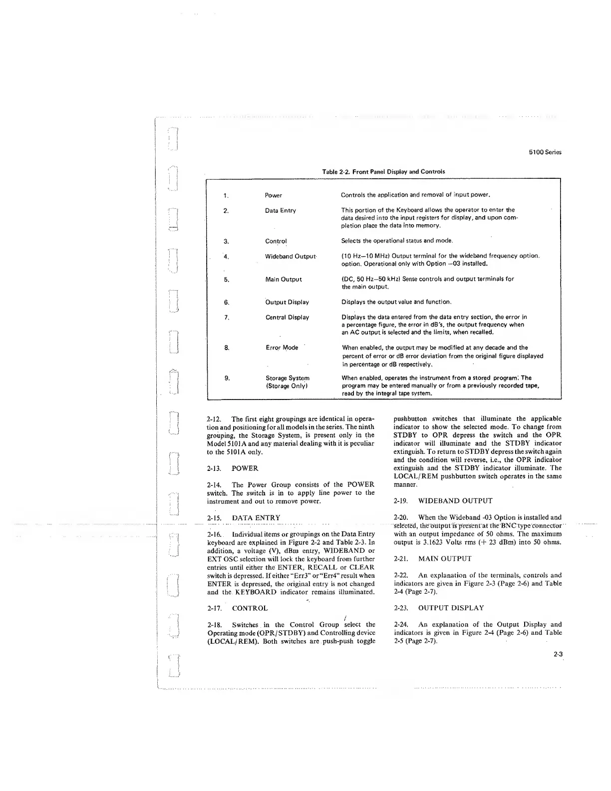
Table
2-2.
Front
Panel
Display
and
Controls
1.
Power
Controls the
application
and
removal
of input power.
2.
Data
Entry This portion
of the
Keyboard
allows
the
operator
to
enter
the
data
desired into the
input registers
for display, and upon com-
pletion place
the data into
memory.
3.
Control
Selects the
operational status
and mode.
4.
Wideband
Output (10
Hz—10 MHz) Output
terminal
for
the
wideband frequency option,
option. Operational
only with Option
—03
installed.
5.
Main
Output
(DC,
50
Hz—50 kHz) Sense
controls
and output
terminals
for
the
main
output.
6.
Output
Display
Displays
the output
value and function.
7.
Central
Display Displays the data
entered
from the data entry
section,
the
error in
a percentage
figure, the
error in
dB's, the output
frequency
when
an AC output
is selected
and the
limits, when recalled.
8.
Error
Mode
When
enabled,
the
output
may be
modified
at any
decade and
the
percent of error or dB error deviation
from
the original figure displayed
in percentage or dB respectively.
9.
Storage
System
{Storage
Only!
When enabled,
operates
the
instrument from
a
stored
program;
The
program
may
be entered manually
or
from
a
previously recorded tape,
read
by
the
integral
tape
system.
2-12.
The first eight
groupings are identical in
opera-
tion and
positioning
for all models in the
series.
The ninth
grouping,
the Storage System,
is present only in the
Model 5101 A and any
material
dealing with it is peculiar
to the 5101 A only.
2-13.
POWER
2-14.
The
Power Group
consists
of the
POWER
switch. The
switch
is in to apply
line
power to the
instrument
and
out to remove power.
2-15. DATA ENTRY
2-16. Individual items or
groupings on the Data Entry
keyboard are explained
in
Figure
2-2
and Table
2-3.
In
addition, a voltage
(V),
dBm
entry,
WIDEBAND or
EXT OSC selection will lock the keyboard
from
further
entries until either the ENTER, RECALL or
CLEAR
switch is depressed. If either “Err3” or“Err4” result
when
ENTER is depressed, the original entry
is
not changed
and the KEYBOARD indicator remains
illuminated.
2-17.
CONTROL
2-18.
Switches in the
Control
Group select the
Operating mode (OPR/
STDBY)
and Controlling device
(LOCAL/ REM). Both
switches are push-push
toggle
pushbutton
switches
that
illuminate the applicable
indicator to
show
the selected mode. To change from
STDBY to OPR depress the switch and the OPR
indicator will illuminate and the STDBY indicator
extinguish. To return to STDBY depress the switch again
and the condition will
reverse,
i.e., the OPR
indicator
extinguish and the STDBY indicator
illuminate.
The
LOCAL/
REM pushbutton
switch operates
in the same
manner.
2-19.
WIDEBAND OUTPUT
2-20.
When the Wideband
-03
Option is installed and
selected, the output is present at the BNC type connector
with an output impedance of 50 ohms. The maximum
output is 3.1623 Volts rms
(+
23 dBm) into 50
ohms.
2-21.
MAIN OUTPUT
2-22.
An explanation of the terminals,
controls and
indicators
are
given
in Figure
2-3 (Page
2-6)
and Table
2-4 (Page 2-7).
2-23.
OUTPUT DISPLAY
2-24.
An explanation of the Output
Display
and
indicators is given in Figure 2-4
(Page 2-6)
and Table
2-5
(Page 2-7).
2-3
 Loading...


