5100 Series
Table
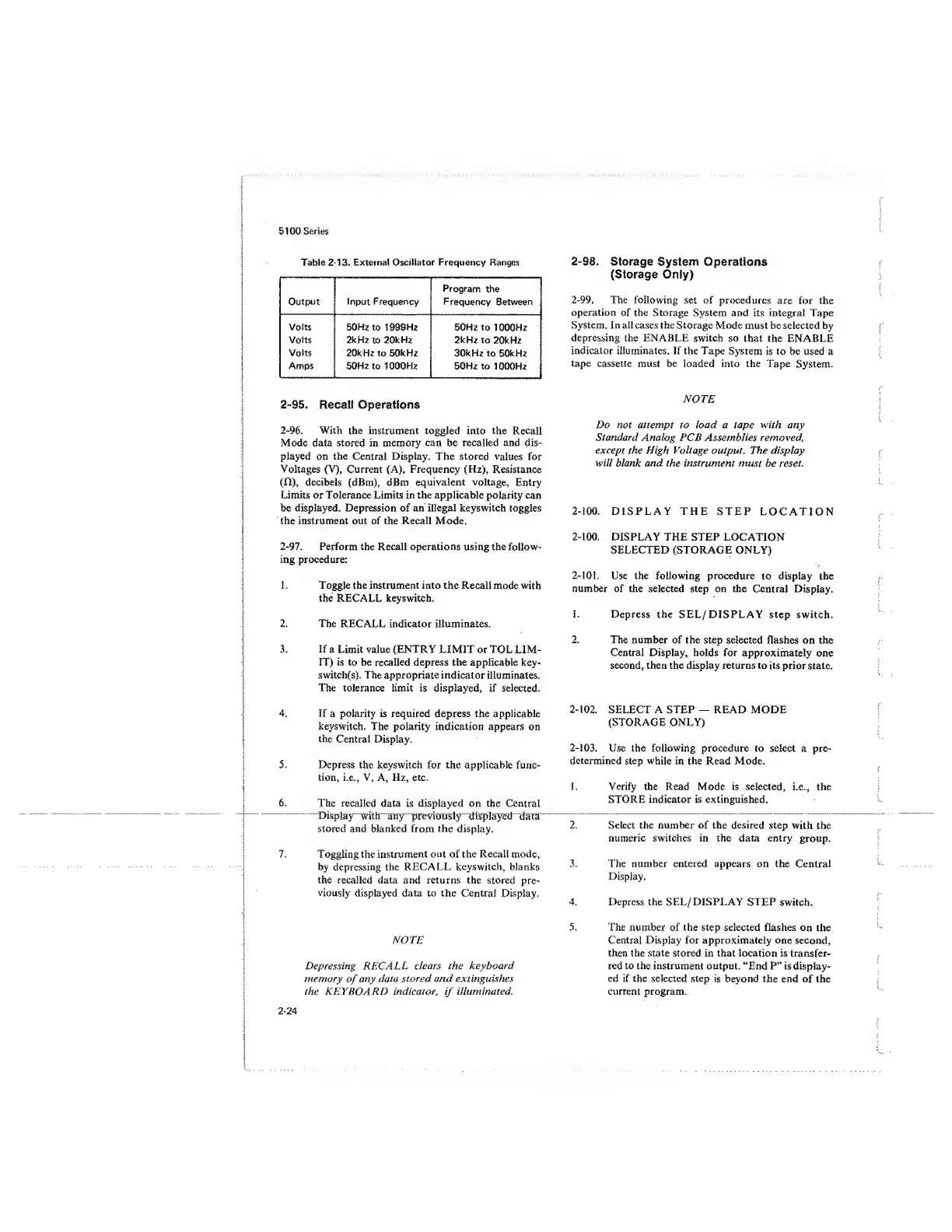
2-13. External Oscillator Frequency Ranges
Output Input Frequency
Program
the
Frequency
Between
Volts
Volts
Volts
Amps
50
Hz to 1999Hz
2kHz
to
20kHz
20kHz to 50kHz
50Hz
to 1000Hz
50Hz to 1000Hz
2kHz
to 20kHz
30kHz to 50kHz
50Hz to
1000Hz
2-95.
Recall Operations
2-96.
With the
instrument toggled
into the Recall
Mode data stored in memory can be recalled and dis-
played on the Central Display. The stored
values
for
Voltages (V), Current (A), Frequency (Hz),
Resistance
(O),
decibels
(dBm), dBm
equivalent voltage.
Entry
Limits or Tolerance Limits in the applicable
polarity
can
be displayed. Depression of an illegal
keyswitch
toggles
the instrument out of the Recall Mode,
2-97.
Perform the Recall operations
using
the
follow-
ing procedure:
1. Toggle the
instrument
into the
Recall mode
with
the
RECALL keyswitch.
2.
The RECALL indicator illuminates,
3. If
a
Limit value (ENTRY LIMIT or TOL LIM-
IT)
is to
be recalled depress the applicable key-
switch(s). The
appropriate
indicator illuminates.
The tolerance limit
is displayed,
if selected.
4.
If a polarity is required depress the applicable
keyswitch. The polarity indication appears on
the
Centra! Display.
5. Depress
the
keyswitch
for
the
applicable func-
tion, i.e., V, A, Hz, etc.
6.
The recalled data is displayed on the
Central
Display
with any previously
displayed
data
stored
and blanked from
the
display.
7. Toggling the instrument
out
of the Recall mode,
by depressing the
RECALL keyswitch, blanks
the recalled data and returns the
stored
pre-
viously
displayed data to the
Central
Display.
NOTE
Depressing RECALL
clears ihe keyboard
memory
of
any
data
stored and extinguishes
the
KEYBOARD
indicator,
if
illuminated.
2-98,
Storage
System
Operations
(Storage Only)
2-99.
The following set of procedures
are for the
operation
of the Storage System and its integral Tape
System. In all cases the
Storage
Mode must be selected by
depressing the ENABLE switch
so that the ENABLE
indicator illuminates. If the Tape
System is to be used a
tape
cassette must be loaded into the Tape
System.
NOTE
Do not attempt to load a tape
with
any
Standard
Analog
PCB Assemblies
removed,
except
the High Voltage
output. The display
will blank and the instrument
must
be
reset
.
2-100.
DISPLAY THE
STEP LOCATION
2-100.
DISPLAY
THE
STEP
LOCATION
SELECTED (STORAGE
ONLY)
2-101.
Use the following
procedure
to
display
the
number
of
the selected
step on
the
Central Display.
S.
Depress the
SEL/ DISPLAY step
switch,
2.
The
number
of the
step selected flashes on the
Central Display, holds for
approximately one
second, then the display returns to
its
prior state.
2-102.
SELECT A STEP
—
READ MODE
(STORAGE ONLY)
2-103.
Use the
following
procedure to select a pre-
determined
step while
in
the
Read Mode.
1. Verify the
Read Mode is selected,
i.e., the
STORE indicator is extinguished.
2. Select the number of the desired
step with
the
numeric switches in the data entry
group.
3.
The number entered appears on the
Central
Display.
4. Depress the SEL/ DISPLAY
STEP
switch.
5.
The number of the step selected flashes
on
the
Central Display for approximately one
second,
then
the state stored in that location is
transfer-
red to
the instrument
output. “End P” is display-
ed if the selected step
is
beyond the end of the
current program.
2-24
 Loading...


