7-46
CORRECTIVE MAINTENANCE
4. The analog A2 PCB and
top
screening are
secured to the bottom cover by two
M3 Torx screws
(item 30). Use a Torx screwdriver
to remove the two screws.
5. Carefully lift the metal
top screening, while pulling it backwards.
6. Pull the battery wiring plug
(item
27)
out of the connector on the analog A2 PCS,
7. Use a Torx screwdnVer
to
loosen
the two black screws [item
13). Do not remove them from the
input unit assembly.
Now analog A2 PCS can be lifted out of the bottom
cover assembly.
8. Fold the analog A2 PCS back
on the
digital
A1 PC6 In the tc^ cover.
9. Lift the bottom cover screening
out of
the
bottom cover assembly.
10. Reinstall the new bottom
cover assembly.
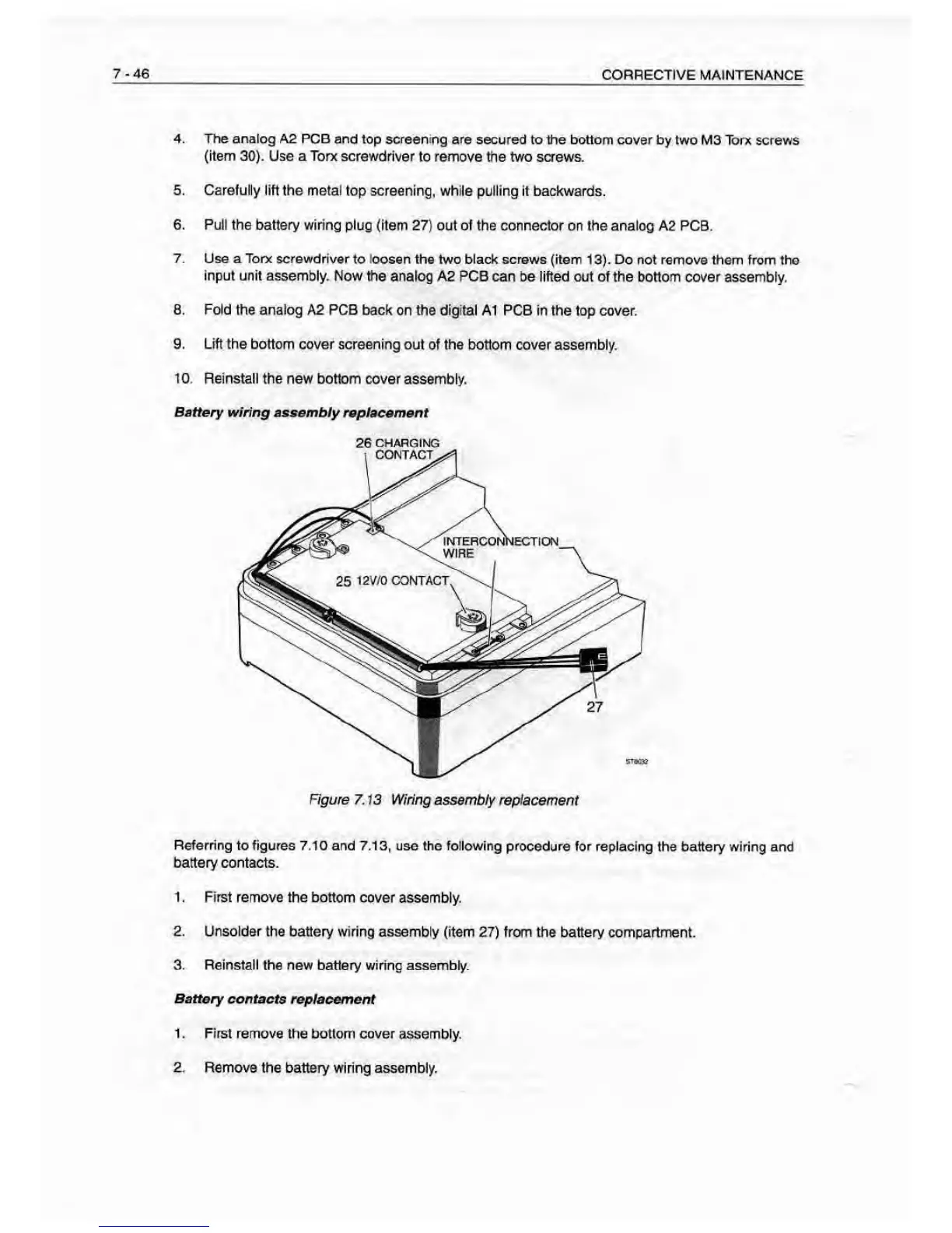
Battery wiring asaemb/y
rop/acement
26
CHAPGIt^
Referring
to figures 7.10 and 7.13, use the following procedure for
replacing the battery wiring and
battery contacts.
1 . First remove the bottom cover
assembly.
2. Unsolder the battery wiring assembly (item
27) from the battery compartment.
3. Reinstall the new battery wiring assembly.
Battery contacts
reptacement
1
. First remove the bottom cover assembly.
2. Remove the battery wiring assembly.