CORRECTIVE MAINTENANCE 7-45
T.S.S.3
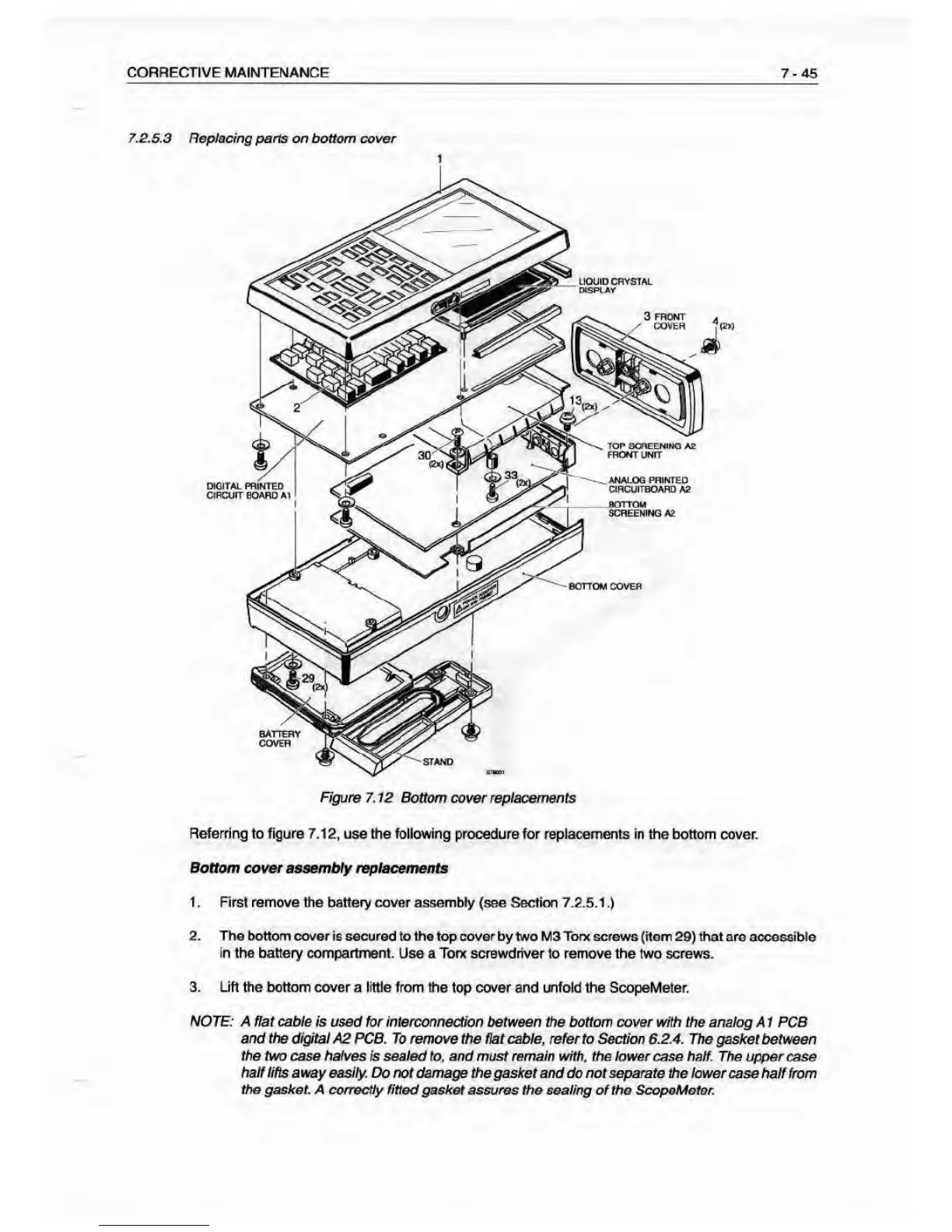
Replacing pans on bottom cover
Figure 7.
12 Bottom cover
replacements
Referring to figure
7.12, use trie following procedure for replacements in the bottom cover.
Bottom
cover assembly replaesmeats
1 . Rrst remove
trie battery cover assembty (see Section 7.2.5.1
.)
2. Trie
bottom cover ie secured to the top cover by two M3 Torn screws (item
29)
that are accessible
in the battery compartment.
Use a Torx screwdriver to remove the two screws.
3. Lift the bottom cover a little from the
top cover and infold the ScopeMeter.
NOTE: A Hat cable
is used for interconnection between the bottom cover with the analog A 1 PCB
and
the
digital
A2 PCB. To remove the fiat cable, refer to Section 6.2.4. The gasket
between
the two case halves f$ sealed
to, and must remain
with,
the lower case half. The upper case
hatf lifts away easily.
Do not damage the gasket and do not separate the lower case half from
the gasket. A correctly fitted
gasket assures the sealing of the ScopsMotor.