Basic Cable Testing
High-Definition Time Domain Reflectometry (HDTDR)
7
7-23
Cable Termination
Because signal reflections can distort the shape of communication signals, the
unused ends of cable segments must be terminated to prevent reflections. The
terminating device is a resistor with a value equal to the cable’s characteristic
impedance. A signal reaching the terminator is neither reflected nor passed: the
signal is absorbed and dissipated by the terminating resistance.
Because the test tool relies on signal reflections to determine cable length, the tool
cannot measure the length of properly terminated cables.
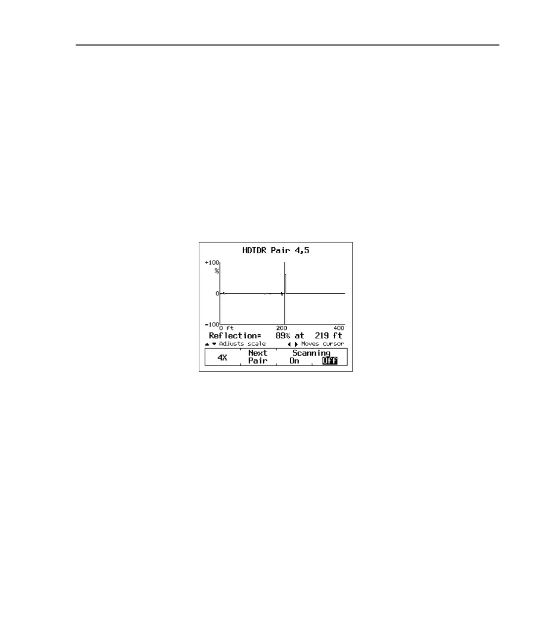
Interpreting the HDTDR Plot
The HDTDR plot has a horizontal scale that represents distance and a vertical
scale that represents the percentage of reflection relative to the original signal, as
shown in Figure 7-13.
oy36f.bmp
Figure 7-13. An HDTDR Plot
Notice that the reflection percentages can be positive or negative. A positive value
indicates that the polarity of the reflection is the same as the polarity of the original
signal. As discussed earlier, positive reflections are caused by abrupt increases in
the cable’s impedance, such as those caused by mismatches in cable types, poor
connections, or breaks in the cable.

 Loading...