Autotest
Autotest Results for Twisted Pair Cable
3
3-19
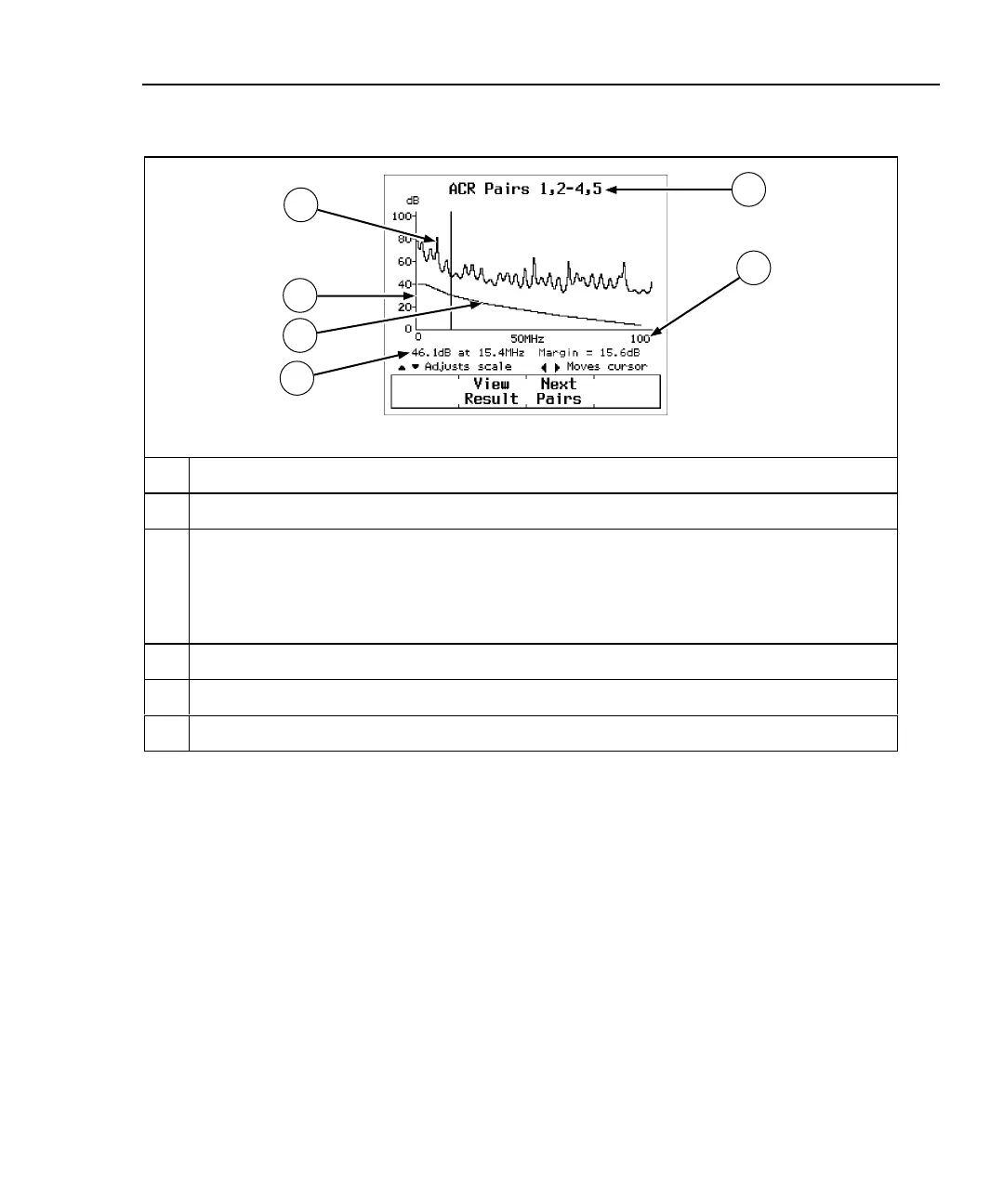
Pressing # View Plot produces the ACR plot screen. Figure 3-7 describes
an example of the screen.
6
5
4
3
2
1
oy12c.eps
1
The cable pairs relevant to the plot.
2
Frequency range in MHz of the ACR test. Use U D to change the frequency scale.
3
The ACR level, frequency, and margin at the cursor’s position. The cursor aligns to the
frequency that produced the worst margin. Margin is the difference between the limit and
measured values plotted at the cursor’s position. Use L R to move the cursor left or right.
If you move the cursor beyond the highest test frequency specified by the selected test
standard, the readout shows the ACR value at the cursor’s position.
4
The ACR limits, as defined by the selected test standard.
5
Decibels of ACR for the cable pair.
6
The calculated ACR for the cable pairs.
Figure 3-7. The ACR Plot Screen

 Loading...