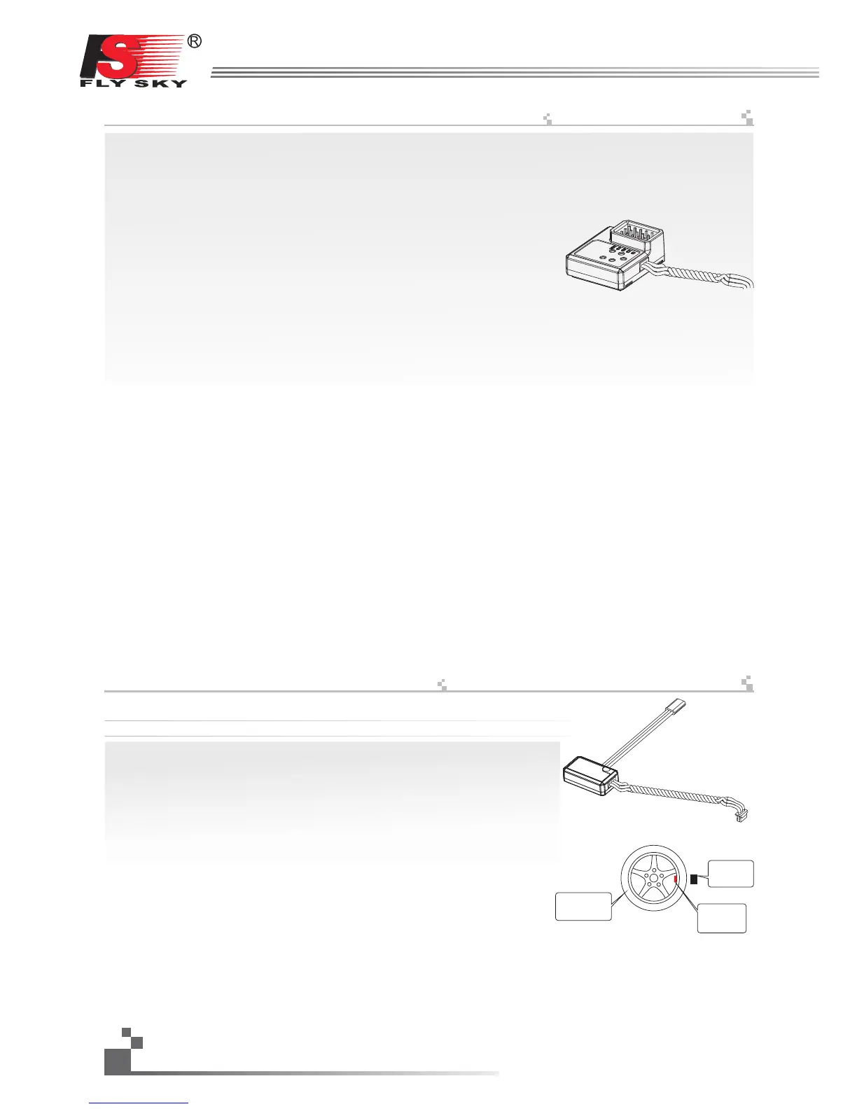
FS-SEV01 serial bus receiver connection instruction
串行总线接收机,最多可串联4个模块,共18个通道;按键K1-K4分别对应C1-C4,用于对相应通道的设定;
操作说明:
1、FS-SEV01接收机的“IN”端口对应接收机的“OUT”端口;
2、FS-SEV01接收机的“OUT”端口,用于串接后级的FS-SEV01接收机,以串
联的方式使用。
3、将此总线接收机插入接收机,打开己配对的 ,接收机电源,LED点亮;
4、操作 触控屏,选择接收机设定的主菜单,进入到舵机设定界面;
5、选择需要扩展的通道,此时,总线接收机的LED熄灭;
6、用对码线上的胶针,按下需要的,相应通道的按键,LED自动点亮,表示设定
成功;
7、插入舵机,检查设定是否成功;
8、重复以上操作即可完成总线接收机4个通道的设定;
9、当需要更多的通道扩展时,只需要在第一级总线接收机的“OUT”端口,串接
新的总线接收机即可,设定的操作方法相同。
发射机
发射机
Data telemetry connection
数据采集模块连接
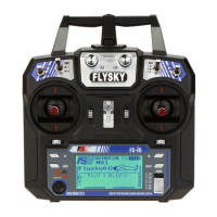
FS-SPD01:磁感应转速采集模块
采集模块的操作使用说明:
操作使用说明:
1、将所配的3PIN插头,一端插入速度采集模块的“OUT”位置,另一端插入
接收机的“IN”位置或接另外的感应器的“IN”位置,如上图所示;
2、将图3的传感器放在磁铁的旁边,磁铁固定在需要测试的轴向转动的地方。
如:模型车的轮毂内侧,如下图所示,传感器与磁铁尽可能的靠近些。
3、打开发射机,接收机电源,在显示屏的接收机窗口内,会发现并显示“
Motor speed 2:0RPM”,试着转动轮子,转速的值会发生变化,则表示安装成功。
http://www.flysky-cn.com
12
磁铁
magnet
串行总线接收机连接说明
Serial bus receiver can connect 4 modules with 18 channels in serial at most. Button K1 and K2 correspond to
C1 and C2 respectively.
Operation:
1. “IN” port of FS-SEV01 receiver corresponds to “Out” port of receiver.
2. The “OUT” port of FS-SEVO1 receiver is used to connect post level FS-SEV01 receiver。
3. Insert the bus receiver to receiver, and then switch on the matched transmitter and receiver. The LED will
be on.
4. Select main menu of receiver setup to enter the interface of servo setup.
5. Select channel which need to be expanded, meanwhile LEDof bus receiver is off.
6. Push relevant channel button by plastic needle of matching line. The setup is successful if LED flashes
automatically.
7. Insert servo to check.
8. Set up 4 channels of bus receiver as above steps.
9. Just connect a new bus receiver with “OUT” port of first stage bus receiver if more channel needed. Set up
the new one as above steps.
Notice:
when the load of serial bus receiver is excessive and electric current is higher than usual, please supply
power directly to the serial bus receiver or it will break cables.
Data operation instruction
FS-SPD01: revolving speed module.
Operation:
1. Insert one end of standard 3 PIN plug into “OUT” port of speed acquisition
module, and insert the other end into “IN” port of receiver or other sensor,
as picture above.
2.
3. Switch on transmitter and receiver. “Motor speed 2:0RPM” will be shown in receiver window in display screen.
Speed value changes as turning wheel, which means installation is successful.
telemetry
Put the sensor beside the magnet as shown in Figure 3; fix the magnet to the position of axle which needs to test.
e.g.: As following picture shows, put the sensor to the magnet as close as possible in the inner wheel hub of car.
注意:当总线接收机的负载过重,电流较大时,请将主接收机的电源分支出来并联接入,单独供电加大负载的能力,
否则可能会因电流过大,烧坏串联的线材。
传感器
Sensor
轮子
Cai wheel