14
注意
请不要将采集模块的"IN"和“OUT”接反,否则发射机将无法识别到该模块及相连的后面的模块的编号.
Notice:
http://www.flysky-cn.com
Don't make IN port and OUT port oppositely, or it will cause that the transmitter can't distinguish each
telemetry module and its following telemetry module(s).
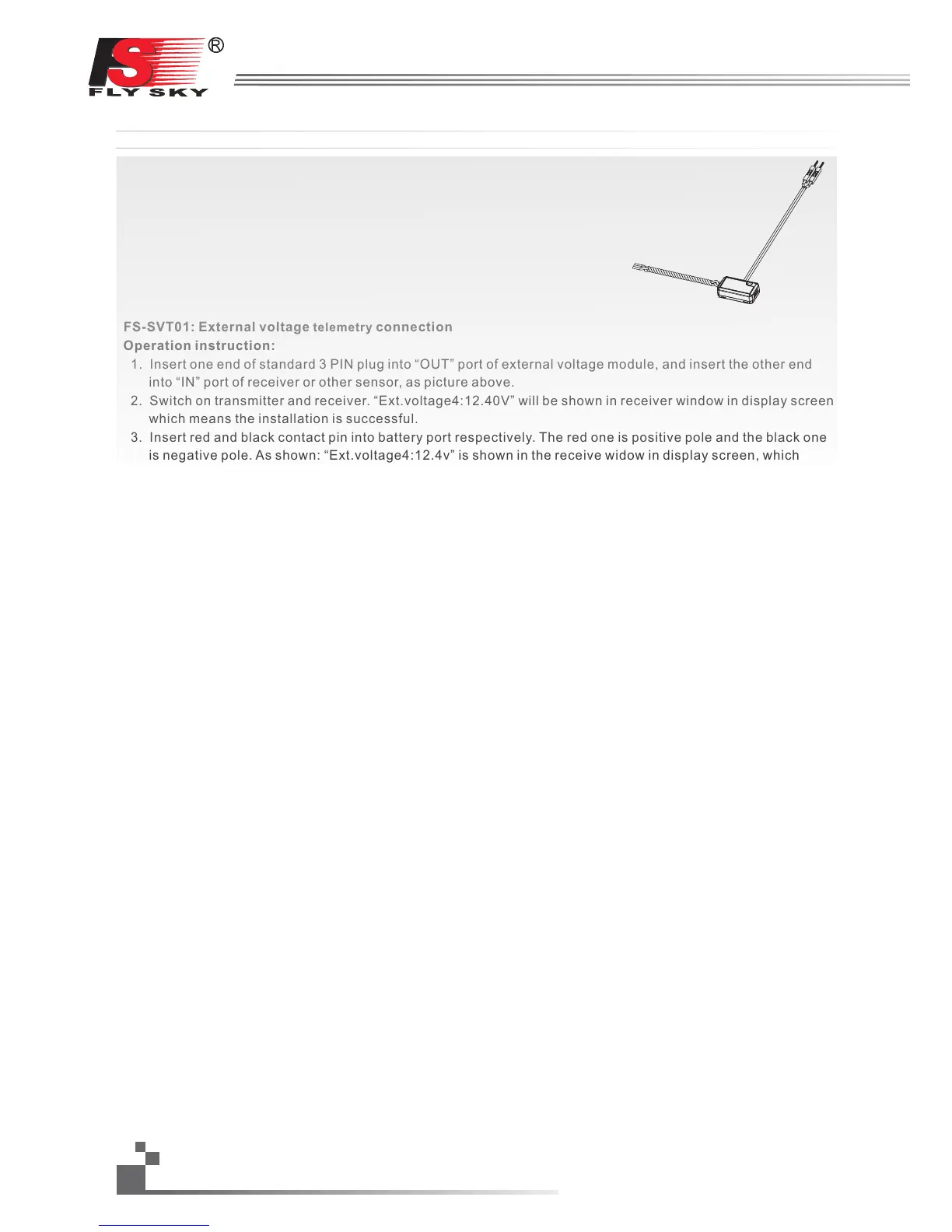
FS-SVT01: External voltage connection
Operation instruction:
1. Insert one end of standard 3 PIN plug into “OUT” port of external voltage module, and insert the other end
into “IN” port of receiver or other sensor, as picture above.
2. Switch on transmitter and receiver. “Ext.voltage4:12.40V” will be shown in receiver window in display screen,
which means the installation is successful.
3. Insert red and black contact pin into battery port respectively. The red one is positive pole and the black one
is negative pole. As shown: “Ext.voltage4:12.4v” is shown in the receive widow in display screen, which
means the tested voltage is 12.4v
Attention: the polarity of red and black line can not be reversed, or the receiver will be damaged.
telemetry
FS-SVT01:外部电压采集模块连接
操作使用说明:
1、将所配的3PIN连接线,一端插入电压采集模块的“OUT”位置,另一端插入接收机
的“IN”位置或接另外的感应器的“IN”位置;
2、打开发射机,接收机电源,在显示屏的接收机窗口内,会发现并显示
“Ext.voltage4:0V”,表示安装成功;
3、将用于检测的红黑线插针分别插入电池的插头内,红色线为正极,黑色线为负极,
如图所示;在显示屏的接收机窗口内,显示“Ext.voltage4:12.40V”,表示己检测
到外部的电池电压为:12.40V。
注意:用于检测的红黑线,不能接反,否则会损坏接收机。
 Loading...