Input Channels
60
VM200 User’s Guide
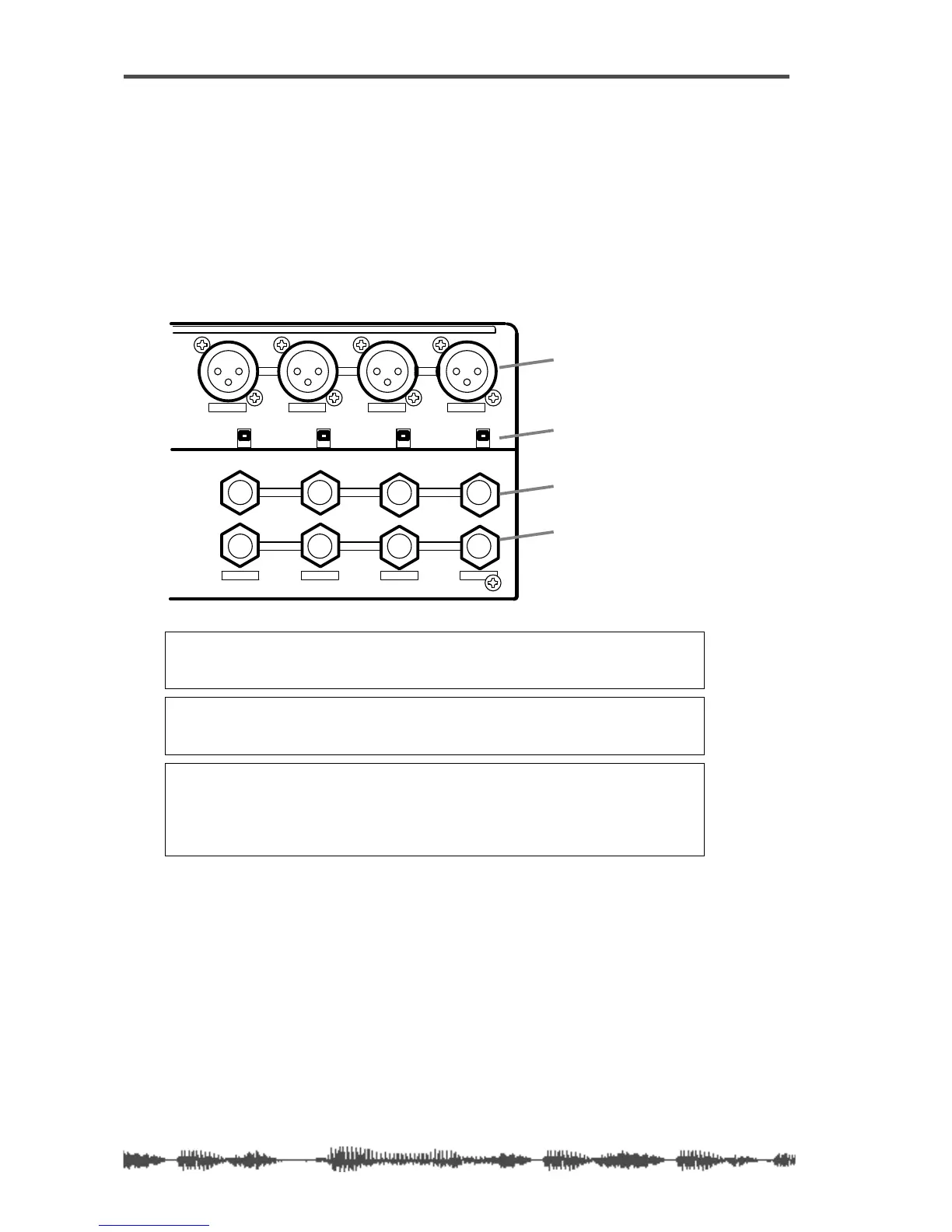
Input Channels 1–4
There are two sets of analog connectors for Input Channels 1 - 4.
The “A” set accepts XLR-type inputs (balanced); the “B” set accepts
phone jacks (balanced or unbalanced).
The XLR connectors are XLR-3-32-type inputs. The phone jacks are
1/4-inch TRS-type.
Both XLR and phone jack inputs accept a nominal input range of
–60 dB to +10 dB.
Note:
Before you set the INPUT A/B switch for input channels 1-4, lower
the corresponding TRIM control to the minimum, or you will hear a clicking
noise.
Note:
Before you turn on phantom power, lower the TRIM control for the
corresponding input channel to the minimum, or turn off the power to the
VM200.
Note:
Turn off the corresponding phantom power switch before you connect
a dynamic microphone; otherwise, you may damage the microphone. If you
turn on the power to the VM200 while the input channel’s phantom power
switch is turned on, the VM200 displays a warning message: “Warning! +48V
SW ON!”
1234
AAA
1234
+48V
OFF
ON
+48V
OFF
ON
+48V
OFF
ON
+48V
OFF
ON
INPUT
INSERT
B
INSERTINSERT
BB
phantom power switch
XLR inputs
phone jack inputs
inserts