F3D3 Series Service Manual Parts Replacement / Section 2.16
Questions? Call Franke Technical Support Group For Your Area. Copyright 2012 Franke, Inc. All rights reserved.
2.16 Main Power ON/OFF Switch Replacement
[See Section 1.5 for Part Number]
1) Disconnect power at outlet. [Pull plug.]
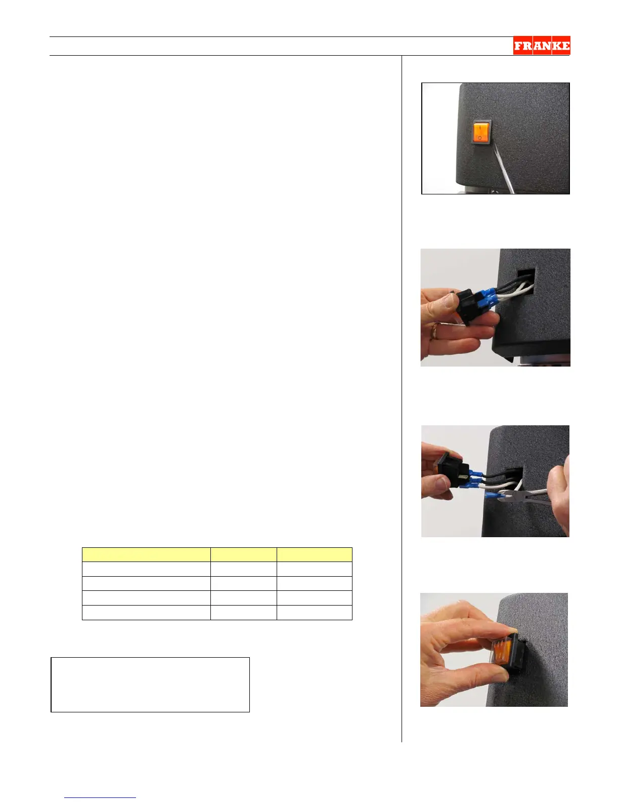
2) Use a flat blade screwdriver to pry under top and bottom
of power ON/OFF switch bezel. Try to depress and
release the plastic locking tabs. [See Photo 1]
3) When free, pull out switch to extent of harness and
remove the four harness wire terminals. On 120-volt
units: two are black and two are white. On 230-volt units:
two are brown and two are blue (neutral). Note switch
terminal positions.
4) Remove new Power ON/OFF Switch from packaging and
attached two hot (black or brown) and two neutral (white
or blue) harness leads to switch terminals marked 1A &
2A and 4B & 5B, respectively. Make sure harness
terminals fully seat on switch bayonet connections.
5) Take switch and gently push harness wires back through
hole, then push switch through that front panel opening
until the top and bottom clips lock it in place. Switch
bezel should be flush with the front panel.
6) Plug in unit power cord to power supply.
Test the new Power ON/OFF Switch by:
7) Switch ON the Main Power Switch. The integrated [red]
pilot light should come on and you should hear the
compressor come on, after a short delay.
8) Press the LANE POWER touch pad. If panel lights come
on, the Main Power Switch is functioning properly.
9) Return Dispenser to normal operating position, if it was
moved in the process.
(Verify Terminal Marking & Wire Color – ALL Models)
Rev. 1 6/2012
[Photo 1] To Remove:
Insert flat screwdriver to release
top & bottom locking tabs.
[Photo 2]
Pull switch out to access
terminals.
[Photo 3]
Remove harness connections
from four switch terminals.
[Photo 4] For Assembly:
Push in new switch until locking
tabs engage & bezel is flush.
6 mm [¼”] flat blade screwdriver
Needle nose pliers