F3D3 Series Service Manual Parts Replacement / Section 2.8
Questions? Call Franke Technical Support Group For Your Area. Copyright 2012 Franke, Inc. All rights reserved.
2.8 Door (Open) Motor Replacement
[See Section 1.5 for Part Number]
1) Roll the unit out to allow access to rear service panel.
2) Disconnect power at outlet. [Pull plug.]
3) Remove the Phillips screws securing rear service access
panel. Lift panel up and off.
4) Straighten, remove and save the cotter pin that secures
the spring (with bushing) to the (left) Door Rotation Block
Pin. Carefully release tension on spring, slide off bronze
end bushing and allow spring to hang from the right side
spring mounting screw.
5) Remove the retaining clip from the right side of the white
plastic Door Cam Link. Remove that link. [You don’t
need to remove the small plastic shaft spacers.]
6) Using the 4 mm [5/32”] Allen/hex wrench, remove the
four motor mounting screws, beginning with the two TOP
screws. [NOTE: Top screws are 5 mm longer than
bottom screws and should be kept separate.]
7) Removing the longer top screws will separate the Door
Open Sensor & Bracket from the motor assembly.
8) Detach the two motor electric power connections.
9) Install new motor assembly starting with the two [shorter]
bottom mounting screws.
10) Remount Door Open Sensor & Bracket using the two
[longer] upper motor mount screws.
11) Reconnect the two motor electric power connections:
[Red to positive; Black to negative].
12) Replace white plastic Door Cam Link, with Stop Screw to
the right side. [NOTE: Make sure bushings and spacers
are on both left and right cam pins, before replacing link.]
13) Attach retainer clip to Door Rotation Block pin.
14) From rear of unit – extend spring to the Door Rotation
Block Pin and slide end/bushing over the pin. Insert
cotter pin through hole in pin and bend cotter pin legs
around pin. Make sure bronze bushing remains in place.
Test the replacement Door [Open] Motor as follows:
15) Plug in unit power cord to power supply.
16) Turn on main power switch and press the LANE-POWER
touch pad on front control overlay.
17) If word: Ready is in display and basket graphic lights are
on, position empty fry basket under hopper and press
against basket bumper switch to initiate fry loading cycle.
18) If Lane properly dispenses fries, replacement Motor and
dispensing assembly is working properly.
19) Re-hang and secure rear service access panel and
return Dispenser to normal operating position.
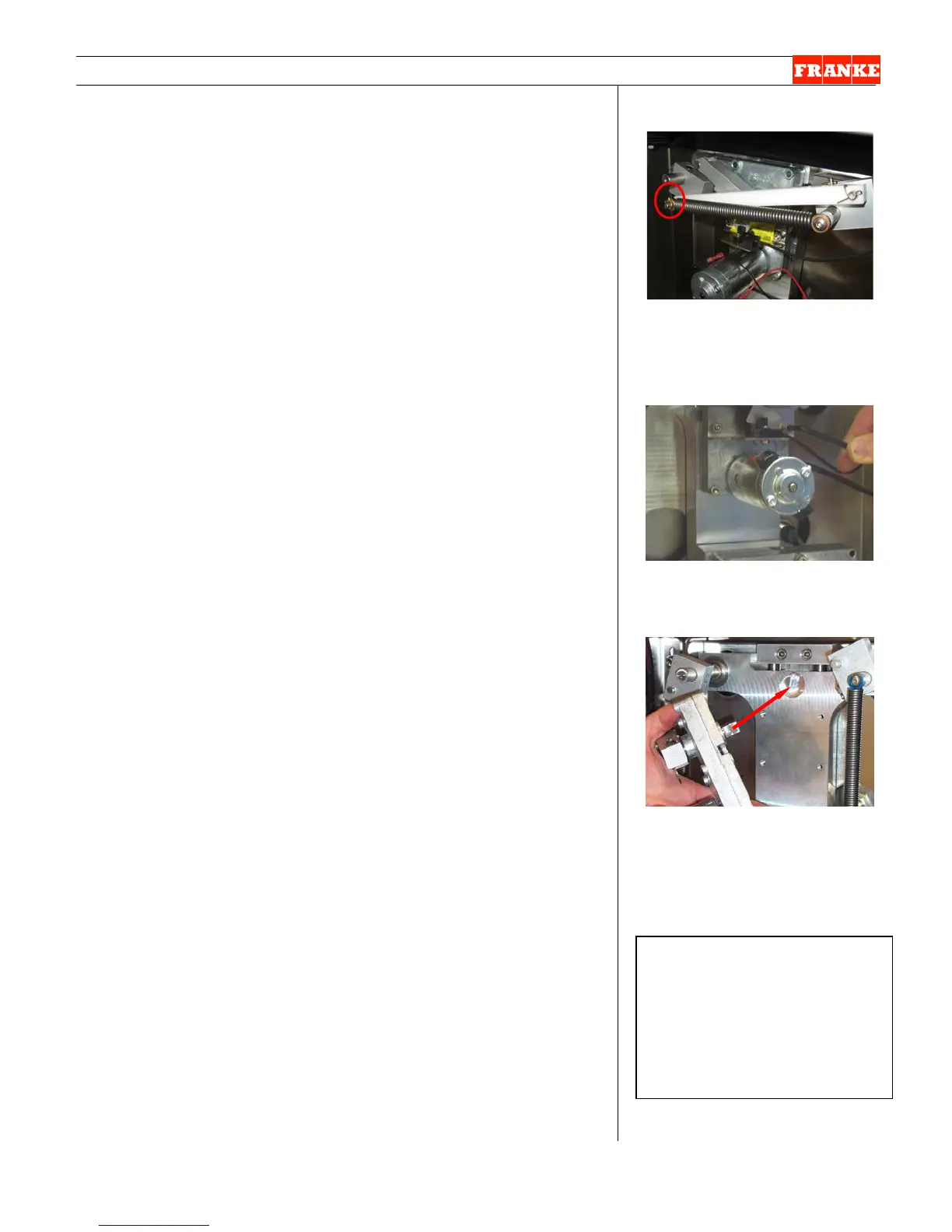
[Photo 1]
Remove the cotter pin retainer
from left side door rotation block
pin then relieve spring tension.
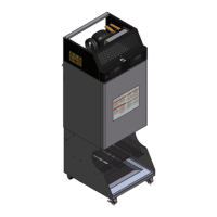
[Photo 2]
Remove the two upper motor
mounting screws first.
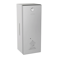
[Photo 3] For Assembly:
Ensure motor drive aligns with
the slot in the slide plate counter
bore.
Rev. 1 6/2012
Medium Phillips
Screwdriver
8 mm [5/16”] box wrench
4 mm [5/32”] Allen/Hex
wrench
Needle-nose pliers