F3D3 Series Service Manual Parts Replacement / Section 2.18
Questions? Call Franke Technical Support Group For Your Area. Copyright 2012 Franke, Inc. All rights reserved.
2.18 24-Volt Power Supply Replacement
[1 ea. on F3D3S & F3D3SP; 2 ea. on F3D3 & F3D3P]
1) Roll the unit out to allow access to rear service panel.
2) Disconnect power at outlet. [Pull power cord plug.]
3) Remove Phillips screws securing rear service access
panel. Lift panel up and out.
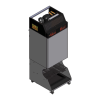
4) Use a medium Phillips screwdriver to remove the four
(two-left, two-right) front control panel mounting screws.
5) Pull panel cover/bezel straight out and allow it to hang
from power switch leads.
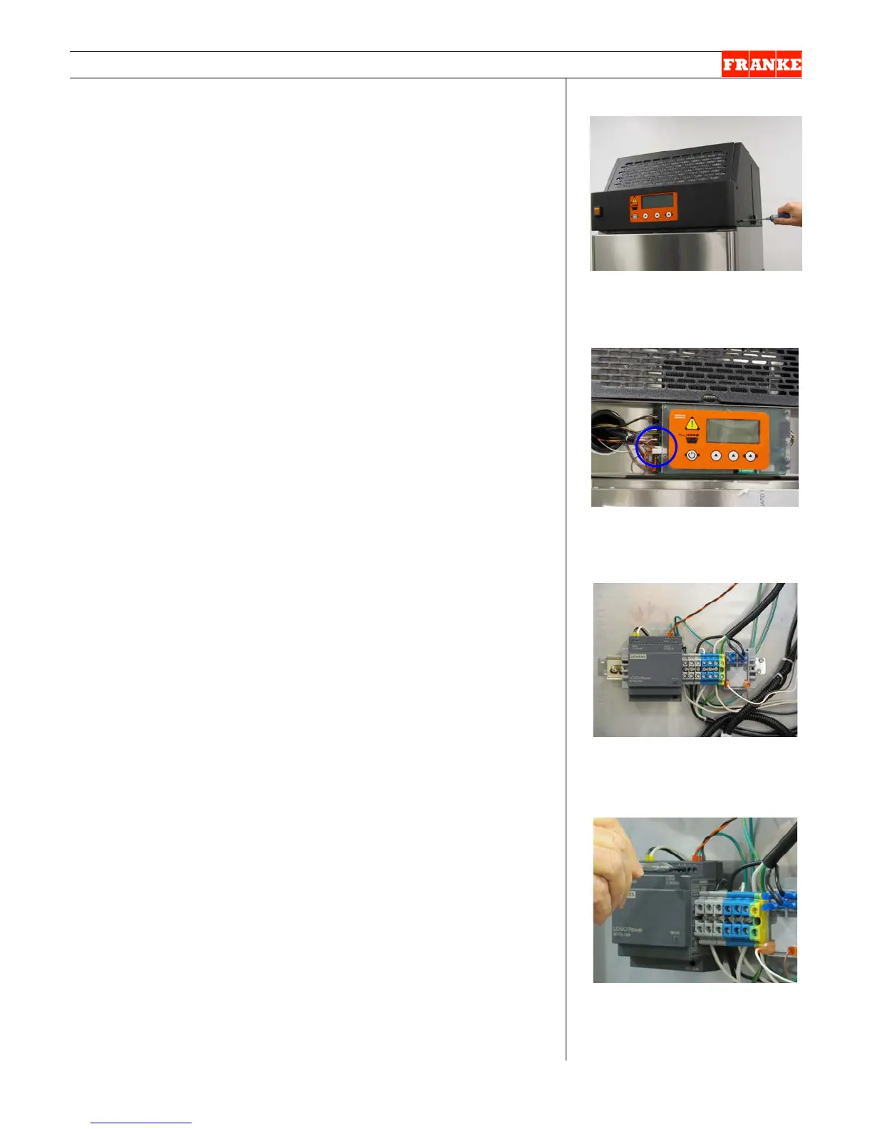
6) Locate 24-volt white plastic connector on left side of
main control board, which is behind the standoff Plexi-
panel mounted touchpad. It is labeled: 24v. Release the
locking tab and remove connector.
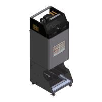
7) From rear of unit - locate the DIN rail mounted 24-volt
power supply(ies).
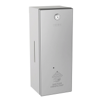
8) Use a 3 mm [1/8”] flat blade screwdriver to disconnect
the black & white [or brown & blue] high voltage wires.
9) Using that same screwdriver, disconnect the smaller
gauge 24-volt red and black leads from power supply,
plus the green/yellow ground wire. NOTE: Propane [P]
models don’t have a green/yellow ground wire here.
10) Using a ¼” [6-7 mm] flat blade screwdriver, depress or
lever downward the plastic release tab, which is located
below and in the center of the power supply. This will
release the power supply from the bottom of DIN rail and
allow you to remove the power supply. [See Photo 5,
page 2]
11) Take new 24-volt power supply [P/N: 19003762] and
position rear slot over upper edge of DIN rail and snap it
down and into place. Make sure it is firmly seated.
12) Reconnect red and black leads on braided harness to
the new power supply. Red = positive, Black = negative.
Attach the green/yellow ground wire to negative (-)
terminal. [No ground here on Propane Models.]
13) Reconnect high voltage wires: Black or Brown to L1,
White or Blue to N.
14) From unit front – attach 24-volt white connector to main
control board (labeled 24v).
15) Position front cover/bezel over lane touch pads and align
with left and right side mounting holes.
16) Secure cover/bezel with the four screws removed earlier.
17) Plug in power cord to power supply.
Test the new 24-volt Power Supply by:
18) Switch ON Main Power Switch at the front control panel.
Continued…
[Photo 1] A F3D3S Model
Remove four front control panel
cover/bezel screws.
[Photo 2]
Disconnect 24-volt power lead at
Main Control Board [24v].
[Photo 3] – From rear
The 24-Volt Power Supply is DIN
rail mounted on back of unit.
[Photo 4]
Use small screwdriver to release
high & low voltage wires from
Power Supply.