31
Installation Manual
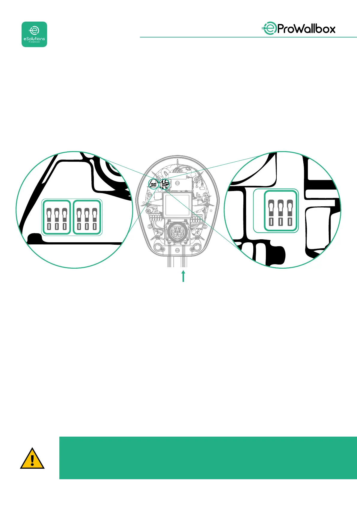
• CN12: port for Accessories installation (refer to the dedicated Accessories
manual)
• CN9/CN10 ports:
• for Master/Slave installation (refer to paragraph 5.1)
• orforEMSconguration(refertothededicatedModbusmanual)
CN9 CN10
GND
+
-
GND
+
-
GND
+
-
CN12
Communication cables connection:
• Remove the protective cap from the communication cables entry point
and insert the corrugated sheath Ø 25 mm.
• Tightenthebox-cablesheathjunction.
• Insert the communication cable, by pulling it to a length that reaches the
communication port leaving some slack.
• To perform a state-of-the-art installation, the communication cables must
pass through the dedicated metal conduit inside the eProWallbox.
• Connect the communication cable to the corresponding port (check the
relevant chapter or the relevant manuals for details on installation of
Accessories or Modbus).
• Repeat the procedure for every communication cable you wish to install.
WARNING
Holes that are not used must be closed using the protective caps
provided to ensure the IP rating.