14
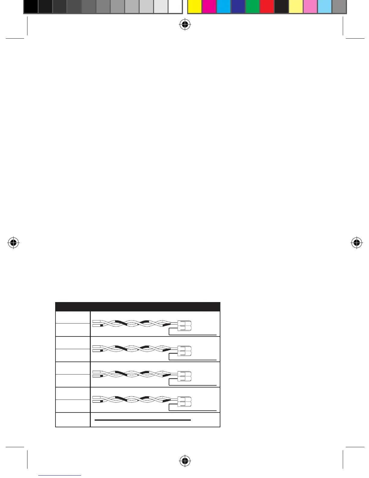
Connection 1
Insert the Orange (V+) wire from the Receiver into a lever connector slot and
close the orange lever on the connector.
Insert the twisted Orange and Green/White Cat 6 wires into the remaining lever
connector slot and close the orange lever on the connector.
Connection 2
Insert the Brown (D+) wire from the Receiver into a lever connector slot and
close the orange lever on the connector.
Insert the twisted Brown and Blue/White Cat 6 wires into the remaining lever
connector slot and close the orange lever on the connector.
Connection 3
Insert the Blue (D-) wire from the Receiver into a lever connector slot and close
the orange lever on the connector.
Insert the twisted Blue and Brown/White Cat 6 wire into the remaining lever
connector slot and close the orange lever on the connector.
Connection 4
Insert the Green (V-) wire from the Receiver into a lever connector slot and close
the orange lever on the connector.
Insert the twisted Green and Orange/White Cat 6 wire into the remaining lever
connector slot and close the orange lever on the connector.
WIRE COLOR LABEL
Orange
Connection 1
V+
Orange
Green/White
Brown
Connection 2
D+
Brown
Blue/White
Blue
Connection 3
D-
Blue
Brown/White
Green
Connection 4
V-
Green
Orange/White
Ground Shield
Wire
GND
Wall Controller Wiring Installation
VPXEMWRT2-Thermostat Manual_pkg.indd 14 2017-12-15 3:37 PM