32
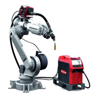
„Robot mode“
configuration -
List of compon-
ents
(10) Upright console
(20) Cooling unit FK 4000-R FC
NOTE! Filler neck, filter and connections for water supply and return must be
on the same side.
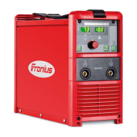
(30) TIG power source TransTig 4000 Job G / F
(31) KD-Digital / LocalNet installation set
(32) Remote control cable 10-pole, 10 m
(40) Interconnecting hosepack W / 2 m / 70 mm²
(40a) LocalNet cable 3.5 m (from Interconnecting hosepack)
(50) Swivel pin receptor installation set VR 4000
(60) Twin-head feeder mount VR 4000
(70) Cold wire feeder KD 7000 D-11
(71) KD-Drive installation set
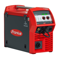
(80) Hot wire power source TransPocket 1500 RC HD
(81) Grounding (earthing) cable 25 mm² / 6 m / hot wire
(82) Connecting cable for TP 1500 RC HD
(90) PlasmaModule 10
(91) Remote control cable 10-pole, 10 m
(100) PlasmaModule holder installation set
(101) Flow watchdog installation set PM 10
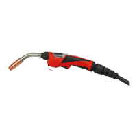
(110) Plasma robot welding torch Robacta PTW 1500 F++ / FG / 4 m
(111) Robacta Plasma KD Drive, 0 - 6 m
(112) Original equipment TIG RO
(113) Hot wire option
(113a) Power cable G / 25 mm² / 6 m / hot wire plasma
(120) Installation set Rob 4000 LocalNet interface
(121) Installation set TIG Rob 4000 cable harness 1.5 m
(130) Installation set Rob 5000 LocalNet interface
(131) Installation set TIG Rob 5000 cable harness 1.5 m
(140) Grounding (earthing) cable 95 mm² / 10 m