23
Signals for robot
welding
(continued)
Power source ready
The “Power source ready” signal remains on as long as PlasmaModule 10 is ready to
weld.
Welding current real value
Via the „Welding current real value“ signal, the actual plasma gas value is indicated by a
voltage of 0 - 10 V on the analog output.
For further information about the signals, refer to the relevant operating instructions for
the robot interface.
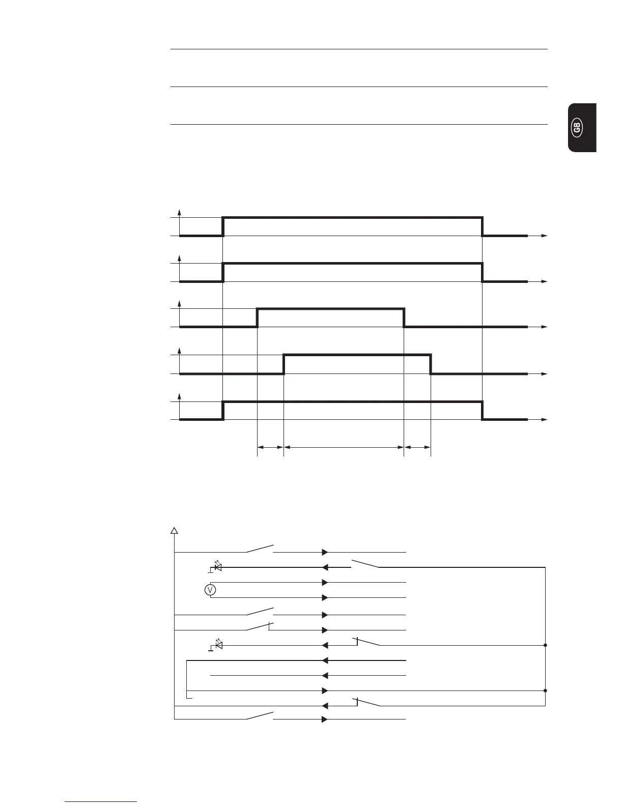
Signal waveform
0
1
0
1
0
1
0
1
Power input value
(power input value)
Robot ready
(robot ready)
Welding start
(welding start)
Arc stable
(arc stable)
Power source ready
(power source ready)
0 V
10 V
t (s)
t (s)
t (s)
t (s)
t (s)
Application
example
Example of how to connect the robot interface to the robot control:
DI Welding start (*)
DO Arc stable (*)
AI Power input value + (*)
AI Power input value - (*)
Not in use
DI Robot ready / quick stop (*)
DO Power source ready
+24 V secondary (*)
GND secondary (*)
Supply voltage (*)
Not in use
DI Welding simulation
X2:4
X2:12
X2:1
X2:8
X2:6
X2:5
X2:14
X12:1
X12:2
X14:1
X2:13
X14:2
+24 V Robot PlasmaModule 10
0 - 10 V
+24 V = Pulse
0 V = Standard
+24 V
GND
or external (+24 V)
+ 24 V
DI = digital in DO = digital out AI = analog in AO = analog out
(*) = required for robot operation
Plasma gas pre-flow time Plasma gas post-flow time
Pilot arc