22
Signals for robot welding
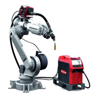
General remarks Robot operation of PlasmaModule 10 requires a robot interface. PlasmaModule 10 can
be controlled via the following interfaces:
- Robot interface ROB 3000
- Robot interface ROB 4000
- Field bus
Signals for robot
welding
Signal I / O ROB 3000 ROB 4000 Field bus
Arc on E x x x
(welding start)
Robot ready / quick stop E x x x
(robot ready / quick stop)
Gas test E - x x
Welding simulation E - x x
(welding simulation)
Power input value E - x x
(power input value)
Arc stable A x x x
(arc stable)
Power source ready A x x x
(power source ready)
Welding current real value A - x x
(welding current real value)
I = input signal (signal from the robot control unit)
O = output signal (signal to the robot control unit)
Overview
Signals for robot-controlled plasma welding operation and their function on the Plasma-
Module 10:
Welding start
starts the pilot arc
Robot ready / quick stop
24 V = Robot ready to weld / 0 V = quick stop; quick stop stops the welding process
immediately
Gas test
activates the Gas Test function on PlasmaModule 10
Welding simulation
The welding simulation signal allows a programmed welding path to be simulated; an arc
and shielding gas are not required.
Power input value
Specifies the plasma gas flow rate; 0 V = minimum plasma gas flow rate, 10 V = maxi-
mum plasma gas flow rate
Arc stable
The „arc stable“ signal is set as soon as a stable arc is present after the pilot arc has
ignited.
 Loading...
